Advertisement
If you have a new account but are having problems posting or verifying your account, please email us on hello@boards.ie for help. Thanks :)
Hello all! Please ensure that you are posting a new thread or question in the appropriate forum. The Feedback forum is overwhelmed with questions that are having to be moved elsewhere. If you need help to verify your account contact hello@boards.ie

help fitting dimmer switches please :)

Options
  • 22-11-2006 4:09pm
    #1
    Registered Users Posts: 13,016 ✭✭✭✭


    just doing a few bits and bobs in the house, and decided to get going with fitting a dobule dimmer switch in the front room, but the existing wiring doesn't seem to make much sense (to me).

    it's a double on/off switch at present with one controlling the main ceiling light in the middle of the room and the other controlling the 2 uplighters either side of the fireplace.

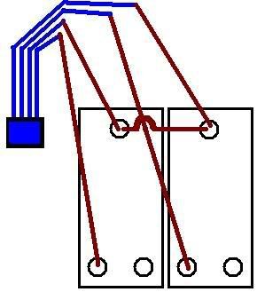
    the weird thing to me is that there are 4 pairs of wires and 4 earth wires (disconnected) behind the switch, with all 4 blue wires connected to each other (via a single chocolate block connection) with one of each of the 4 brown wires in each of the 4 connectors on the switch with a short length of brown wire bridging the top two connections together.

    my problem now is that the double dimmer switch just has 3 connections for pos/neg/earth on each of the two switches and I'm not sure where to start.

    I was only expecting to find 3 pairs of ca\bles and I don't know what's what any more.

    does anyone have any idea how to get this set up correctly?

    thanks in advance. :)

    P.S> yes the power is off. ;)


Comments

  • Registered Users Posts: 397 ✭✭Doolittle51


    If i understand your post correctly you have:
    4 brown wires going to your existing switch
    4 blue wires connected together but not connected to the existing switch
    4 earth wires connected together but not connected to the existing switch

    So:
    The brown wires which are looped on your existing switch are live. They will have to go to the live connections on your new switch, and keep them looped.

    The other brown wires going to your existing switch are the 'switched live' cables (they are live when the switch is on and they go to your lights)
    So these will go to the 'out' terminals on your new switch.

    And the earth wires which are coiled up behind your existing switch can be used for the earth for your new switch.

    The blue wires connected together are just the neutrals, and aren't required.

    Hope this is clear to you?


  • Registered Users Posts: 13,016 ✭✭✭✭vibe666


    here's how it looks at the moment. the earth's are not connected to anything except each other.

    I'm starting to think this house is wired up just a tad strangely.

    i took it to bits to have a look at it and try and get the dimmer working but failed miserably, and in doing so, found out that all the downstairs lights are wired together. i have the two lights either side of the fireplace working, but none of the downstairs lights work at all apart from that.

    i'msure with a little messing i can get them working again, but i kinda ran out of light and my torch battery went flat just as i got to the stage I'm at now.

    NewJpegImage.jpg


  • Closed Accounts Posts: 783 ✭✭✭Skellington


    quickest way to sort it would be to turn power on (be careful) and touch any two cables together until the light under the stairs works. then you'll have your feed and loop feed, stick one of those two into each terminal on your switch marked 'c' or 'com' and put a link in between them. now stick the two remaining browns into the 'L1' of each dimmer. that should be it, they should work fine then.


  • Registered Users Posts: 27,164 ✭✭✭✭GreeBo


    you will probably find that one of the brown wires (the live, not switched live) will continue on to your next light switch and so on and so on for the lightintg circuit.

    If you didnt take a picture and label each wire before you disconnected them then you are in for some annoying work figuring out which is which, especially if its a two way switch as you will have to have it all connected correctly before the switch will work.
    The little joining piece of brown is to give a "live in" to the other switch, otherwise only one switch will have power.

    The two connection at the top of your drawing are the "live in"'s
    The double connections below will be called L1 & L2 or C1 & C2 or something like that.
    Connect the live out to 1 if you just want a normal switch.
    If you want a two way switch you need to connect a second wire from 2 to 2 on the next switch and the same for 1.

    As was said, the earths in a house are all connected so thats fine.
    If you switch has an earth connection (which it may not if its all plastic) or if the box has one (which it also may not) you will know them as they are brass and away from everything else.
    If they earths are all loose I would connect them together, otherwise you might be breaking the earth continuity in your house and some sockets/applicances may not be earthed.
    The neutrals are also all connected together, they are only required at the bulb, not the switch.

    - First find the main "live in" and label as such (turn on power and touch phase tester to all brown wires)
    - Then find the live the continues to the next switch and again label.
    (connect other brown wires in turn to the live in and turn on all the other switches in our house (on the same level, up or downstairs) when something else turns on you have found it.
    - next you need to find which live out goes to which light, if you only have two lights then you have a 50/50 chance of getting it right first time, but you wont :)

    Let us know if you have any probs


  • Registered Users Posts: 13,016 ✭✭✭✭vibe666


    well, will a little luck and logical deduction I managed to get back to where I started, with the original ouble switch working along with all the downstairs lights so I was wondering if it should be as simple as just transplanting all my wires from the old to the new switch in their current configuration, i.e. leaves all the blue wires where they are and find the equivalent L1's and L2's etc. on the new and old and move from one to the other.

    the only real problem i can see is that all the wires are of the thick solid copper type, not the bunch of tiny wires type (i'm sure they have a name :-) and I don't think there is the room in the new switch for all the wires.

    maybe a bit of creative chocolate blocking is in order to save the day.


  • Advertisement
  • Registered Users Posts: 84 ✭✭Beach Head


    One wire comming in to the box will be the main live, nuetral and earth for that circuit, looped to the main live, nuetral and earth for the next switch and so on. The other two wires are live nuetral and earth for the main ceiling light in that room and the live nuetral and earth for the wall lights.

    All of the blue (Nuetral) wires should be connected together in a connector block. These wires should not be connected to the switch or anything else but each other. This ensures continuity of the circuit throughout the house.

    All of the earth wires should be also connected together. This ensures that there is an earth available at every light fitting and switch elswhere if you need it. If the box that the switch is screwed to is metal, an earth wire should be connected to it (There will be an earth terminal on the back of the box) Same for the dimmer, if its metal, it needs an earth. ALWAYS make sure that the earths are connected together, do not try to fit them all in one little terminal if they do not fit, put them in from both sides or loop from the box to a larger connector etc. DO NOT leave any earth wire unconnected to another. Just because it may not be doing anything in your switch does not mean that it is not needed somewhere else.

    Now, the switch connections, on your switches there should be a C L1 and L2. Connect the live(Brown) wires that are currently looped together in your standard switch to the two C terminals of your dimmer. Now connect one of each of the brown wires that are left to L1 on each switch. L2 should not have to be used. No creative "chocolate blocking" is required, the cable is 1.5 copper and will fit into the dimmer connections. If it is currently folded back on itself in the current switch tterminal you may have to just snip off the folded piece of copper.

    One last thing, if you are not sure about what you are doing, contact an electrician, its not like plumbing etc, your house might just flood, screw up electrical connections and people can get badly hurt.


  • Registered Users Posts: 84 ✭✭Beach Head


    One wire comming in to the box will be the main live, nuetral and earth for that circuit, looped to the main live, nuetral and earth for the next switch and so on. The other two wires are live nuetral and earth for the main ceiling light in that room and the live nuetral and earth for the wall lights.

    All of the blue (Nuetral) wires should be connected together in a connector block. These wires should not be connected to the switch or anything else but each other. This ensures continuity of the circuit throughout the house.

    All of the earth wires should be also connected together. This ensures that there is an earth available at every light fitting and switch elswhere if you need it. If the box that the switch is screwed to is metal, an earth wire should be connected to it (There will be an earth terminal on the back of the box) ALWAYS make sure that the earths are connected together, do not try to fit them all in one little terminal if they do not fit, put them in from both sides or loop from the box to a larger connector etc. DO NOT leave any earth wire unconnected to another. Just because it may not be doing anything in your switch does not mean that it is not needed somewhere else.

    Now, the switch connections, on your switches there should be a C L1 and L2. Connect the live(Brown) wires that are currently looped together in your standard switch to the two C terminals of your dimmer. Now connect one of each of the brown wires that are left to L1 on each switch. L2 should not have to be used.


Advertisement