Advertisement
If you have a new account but are having problems posting or verifying your account, please email us on hello@boards.ie for help. Thanks :)
Hello all! Please ensure that you are posting a new thread or question in the appropriate forum. The Feedback forum is overwhelmed with questions that are having to be moved elsewhere. If you need help to verify your account contact hello@boards.ie

Wiring a phone extension

Options
  • 29-08-2007 12:47am
    #1
    Closed Accounts Posts: 4


    Hi,

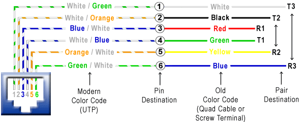
    I have a phone socket downstairs which my broadband router is currently connected to but I want to move it upstairs. I have three blank sockets upstairs & there are three wires behind the phone socket downstairs so I presume the three sockets upstairs are wired back to the socket downstairs. There are four wires comming into the socket downstairs from outside (green, orange white and brown) Orange is connected to L1 on the socket, green is connected to L2 on the socket and the other two are not connected to anything. I have wired one of the sockets upstairs according to:
    jack-diagram.gif

    Just wondering what do I need to do with the wire downstairs to make it work? The wire from upstairs is made up of a blue wire, an orange wire, a white wire with blue stripe and an white wire with orange strip. Is it just a matter of connecting 2 of these wires to L1 and L2 also? I tried a few combinations but none of them seemed to work.


Comments

  • Registered Users Posts: 10,952 ✭✭✭✭Stoner


    Ike, if the three wires at the back of the box downstairs are indeed the other end of the three cables you have upstairs, then the job is easy.

    The phone cables are connected in parallel. You only need two cores for a phone to work. On most phone systems there are four cables to connect, but the inside two connections are all that are needed.

    First start with an analogue phone at the working socket,
    open up the downstairs phone socket and identify the working pair of phone cables, these are the two cable you need.

    Lets say that the existing working pair are red and green, then simply strip all the other three cables and join up these two colours to the existing working pair.

    You should then have four red cables joined and connected into the existing phone point and four green cables connected into the existing phone point.

    Upstairs you then need three phone sockets (about €3 each) strip the cables and connect the red and green cables into the inside terminals of each phone socket, test as you go.

    I love the diagram, but it is really just a case of identifying the working pair and sharing this pair to the other three points.


  • Closed Accounts Posts: 4 ike_1


    Thanks for the reply Stoner. When you say the inside two connections -how do I identify the inside two connections? Also which are the inside two terminals? I have attached an image of the wired socket upstairs (sorry about the quality).

    Thanks again.


  • Registered Users Posts: 438 ✭✭wasim21k


    i attached file follow those two pints to ur cable.


  • Registered Users Posts: 10,952 ✭✭✭✭Stoner


    Hi Ike,

    The best way to check this is to take the back off the socket as you have.

    Then plug an analogue phone into the socket (any regular house phone)
    Check that it works (it should) Then remove the cables one at a time, just check until you get a working pair.

    With the push in connection you have you may need to get two connectors, and join the paired cables together (two sets of four) then take a clean pair about 150mm long to the phone socket, this type of phone socket will not take 4 cables pushed into it


  • Registered Users Posts: 10,952 ✭✭✭✭Stoner


    very quick pic of what your joint sould look like.


  • Advertisement
  • Registered Users Posts: 438 ✭✭wasim21k


    ooh there is more easy way,
    first top left and right wire is two middle pair. as you can read numbers on socket pcb.


Advertisement