Advertisement
If you have a new account but are having problems posting or verifying your account, please email us on hello@boards.ie for help. Thanks :)
Hello all! Please ensure that you are posting a new thread or question in the appropriate forum. The Feedback forum is overwhelmed with questions that are having to be moved elsewhere. If you need help to verify your account contact hello@boards.ie

Excellent Post , Forum Index

Options
  • 16-10-2008 11:57pm
    #1
    Registered Users Posts: 10,952 ✭✭✭✭


    As part of the forum housekeeping plans we are adding in a thread with an index of decent threads that that deal with frequent questions, demos and training etc. It should help keep sickies down and keep the better threads alive.


    Forum shake up


«1

Comments

  • Registered Users Posts: 10,952 ✭✭✭✭Stoner


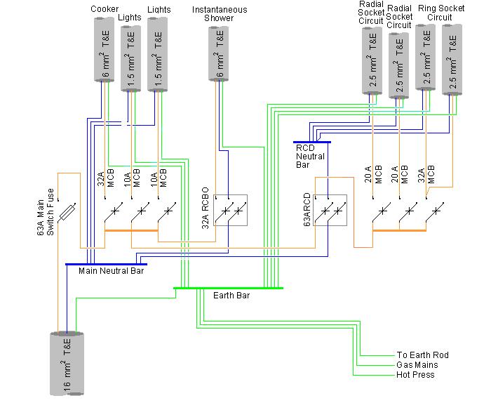
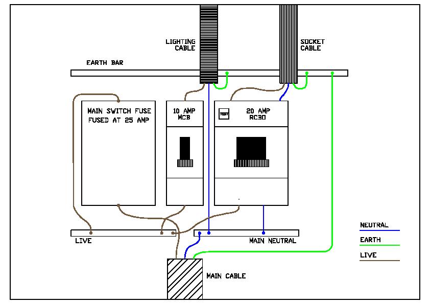
    Ok first up is a couple of circuit diagrams for distribution units // consumer units//fuseboards, one for house , and one for a shed.

    House unit thanks to fishdog,


  • Registered Users Posts: 10,952 ✭✭✭✭Stoner


    dist_board.jpg


  • Registered Users Posts: 10,952 ✭✭✭✭Stoner


    [IMG][/img]shed_board.jpg


  • Registered Users Posts: 10,952 ✭✭✭✭Stoner


    Instructions on how to adjust a Horstmann Economy 7, storage heating timer.


  • Closed Accounts Posts: 1,113 ✭✭✭fishdog


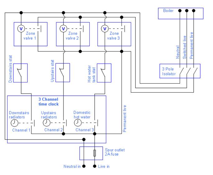
    Here is a control arrangement that I have often used when installing 3 zone valves to be controlled by a 3 channel time clock. It is very simple to use and also very efficient. This is because an individual zone can be selected and switched on independently. The boiler can heat 1 zone on its own far quicker than it can heat 3 zones at the same time. Often it is desirable to heat just hot water for a bath or just the radiators downstairs etc. Connecting stats to the zone valves ensures that once the boiler has reached its set point it will switch off even if the time clock is “calling” for it thus using the boiler to a minimum saving expensive fuel.

    Note: When the zone value operates it is the auxiliary connections on the valve that switches on or off the boiler. The auxiliary connection wires are often colored orange and grey and not polarity conscious. Any zone valve switching on will then switch on the boiler with this dry contact.

    Fishdog_Heating_Control.jpg


  • Advertisement
  • Closed Accounts Posts: 1,712 ✭✭✭davelerave


    i noticed recently that the contacts on the sunvic 4-wire motorized valves anyway are indeed polarized ie. the permanent live has to go to the grey


  • Closed Accounts Posts: 1,113 ✭✭✭fishdog


    the contacts on the sunvic 4-wire motorized valves anyway are indeed polarized ie. the permanent live has to go to the grey

    I am not familiar with this make, perhaps with different types of valves than the ones shown and a different circuit arrangement this is the case.

    As can be seen in the drawing above there is no electrical connection between the actuator wires and the wires for these contacts. That is why I described them as “dry contacts”. These contacts merely make when the valve physically turns to the on position, (even if this is done manually) and break when the valve physically turned to the closed position. This will happen regardless of voltage being present or not and regardless of polarity. That is why the connections shown are not polarity conscious.


  • Closed Accounts Posts: 1,712 ✭✭✭davelerave


    No problem i use the same circuit i only noticed this recently on these particular valves


  • Registered Users Posts: 27,164 ✭✭✭✭GreeBo


    Stoner wrote: »
    dist_board.jpg

    Thx for the diagrams, very useful.
    Where would the shed "outlet" go in this diagram?


  • Registered Users Posts: 10,952 ✭✭✭✭Stoner


    well something taken off a similar connection as the Cooker (32Amp). this would be a 6sq cable and it would feed the small counsumer unit in the post above that.


  • Advertisement
  • Closed Accounts Posts: 2,389 ✭✭✭Carlow52


    In this thread
    http://www.boards.ie/vbulletin/showthread.php?t=2055427313 Post No 23 it is recommended that the fire detection system shut down the MHRV in the event of a fire.

    Perhaps someone might pen a few lines on what this requires in terms of kit and sketch/explain how it might be wired.
    Thanks.


  • Closed Accounts Posts: 1,712 ✭✭✭davelerave


    a commercial panel will have a changeover contact for this .the regular domestic mains smoke alarms can be fitted with a relay base(nb:relay base w/battery backup) to do the switching .so basically you need a twin brown to any interconnected smoke base(for domestic) .this twin brown will go back to a relay at the fusebox or back to the mhrv panel to switch off the system in event of fire
    http://www.eielectronics.com/Userfiles/ei128rbu_datasheet.pdf
    i'm not familiar with mhrv(i work mostly with geothermal and regular boilers etc.)but linking the contact back to the mhrv panel would be preferable if this connection is available at the mhrv


  • Registered Users Posts: 14 fluke-it


    I'm wiring a house with solar panels, I think I would need a 3 channel time clock because the radiators upstairs can be turned on separate to the radiators downstairs, plus the hot water must be switched separately. There is also a stove which will heat water and radiators. the burner must cut out when the copper cylinder reaches a certain temp, I will probably need relays for this, Does anyone have any circuit diagrams for a heating system similar to this? any help is much appreciated.


  • Closed Accounts Posts: 1,113 ✭✭✭fishdog


    I think I would need a 3 channel time clock
    Sounds right
    the radiators upstairs
    1 channel
    separate to the radiators downstairs
    2 channels
    hot water must be switched separately
    3 channels. Use the diagram I posted for this and it will work.
    There is also a stove which will heat water and radiators
    That is fine. I guess the stove is a solid fuel back boiler sort of thing??? You will need a pipe stat controlling a circulation pump for this. It will simply heat domestic hot water and radiators as you say, so if the time clock calls for heat, but the system is hot enough the boiler will not start.


  • Closed Accounts Posts: 1,712 ✭✭✭davelerave


    fishdog wrote: »
    davelerave:
    That is a good idea.

    I did a restaurant a while ago that and I connected an output from the fre alarm panel to a slam valve for the gas to the building. In the event of the fire alarm panel activating the gas supply would be switched off outside the building.
    who suggested this ?building regs should require it .it's up to the gas installer to fit the valve and ask sparkie to hookup.not the sparkies problem if not fitted.it seems to be overlooked a lot on small commercial jobs
    afaik.


  • Registered Users Posts: 155 ✭✭Adam anto


    Thanks for the thread. Trip switch panel diagram is very helpful....


  • Registered Users Posts: 350 ✭✭tommyh1977


    fishdog wrote: »
    Sounds right

    1 channel

    2 channels

    3 channels. Use the diagram I posted for this and it will work.


    That is fine. I guess the stove is a solid fuel back boiler sort of thing??? You will need a pipe stat controlling a circulation pump for this. It will simply heat domestic hot water and radiators as you say, so if the time clock calls for heat, but the system is hot enough the boiler will not start.


    Just regarding the Back Boiler - i have same issue. I understand fully the operation of the 3 zone system (spark by trade), however if i use a pipe stat and circulating pump for back boiler, what happens when pump cuts in if all valves are in the off position i.e. closed. Surely the water cannot circulate and would start to boil. I was thinking if the pipe stat also turned on a bypass valve with the circulating pump, so basically this valve only allows flow thru the zone when pump is on?
    Cheers for the diagram by the way, spot on.


  • Closed Accounts Posts: 2,389 ✭✭✭Carlow52


    tommyh1977 wrote: »
    Just regarding the Back Boiler - i have same issue. I understand fully the operation of the 3 zone system (spark by trade), however if i use a pipe stat and circulating pump for back boiler, what happens when pump cuts in if all valves are in the off position i.e. closed. Surely the water cannot circulate and would start to boil. I was thinking if the pipe stat also turned on a bypass valve with the circulating pump, so basically this valve only allows flow thru the zone when pump is on?
    Cheers for the diagram by the way, spot on.

    [Have not read rest of this thread so if already stated..]

    The back boiler circuit MUST have an open vented pipe [ typically 3/4 or larger] up into the attic space where it loops into the header tank. This means that in the event of a power failure the water can circulate under gravity and if it boils it will go into header tank..

    I cannot agree with the auto bypass suggested by Gary71 when the heat source is a back boiler.

    Fitting a back boiler to a fully closed system is dangerous.


  • Posts: 0 [Deleted User]


    Carlow52 wrote: »
    [Have not read rest of this thread so if already stated..]....
    DOH... that i'll teach me to employ speed reading techniques
    Carlow52 wrote: »
    [I cannot agree with the auto bypass suggested by Gary71 when the heat source is a back boiler..
    Being a gasman when i read back boiler i think Baxi, that's my excuse anyway:), Gary


  • Registered Users Posts: 350 ✭✭tommyh1977


    Carlow52 wrote: »
    [Have not read rest of this thread so if already stated..]

    The back boiler circuit MUST have an open vented pipe [ typically 3/4 or larger] up into the attic space where it loops into the header tank. This means that in the event of a power failure the water can circulate under gravity and if it boils it will go into header tank..

    I cannot agree with the auto bypass suggested by Gary71 when the heat source is a back boiler.

    Fitting a back boiler to a fully closed system is dangerous.

    Yes it is a vented system, however i seem to be lost somewhere. If all valves are closed then how can the system circulate under gravity, i can understand this principal if there was no motorised valves in the system.
    Appreciate all the help.


  • Advertisement
  • Registered Users Posts: 350 ✭✭tommyh1977


    tommyh1977 wrote: »
    Just regarding the Back Boiler - i have same issue. I understand fully the operation of the 3 zone system (spark by trade), however if i use a pipe stat and circulating pump for back boiler, what happens when pump cuts in if all valves are in the off position i.e. closed. Surely the water cannot circulate and would start to boil. I was thinking if the pipe stat also turned on a bypass valve with the circulating pump, so basically this valve only allows flow thru the zone when pump is on?
    Cheers for the diagram by the way, spot on.


    Sorry if i did not explain my idea correctly. Basically what i was thinking of doing was placing another motorised valve in parallel with the motorised valve of one of the heating zones, therefore if that zone and all other zones are closed, when back boiler pipe stat switches the pump on then it would also open this parallel valve to allow flow and then switch off again when pump cuts out. Maybe this is a ridiculous idea, as i am a spark not a plumber.

    Cheers


  • Closed Accounts Posts: 4,431 ✭✭✭M cebee


    zone valves 'only' probably not allowed for back boiler(i'm a sparkie )

    'systemlink' or maybe open loop for cylinder coil+zone valve for rads might be used with backboiler afaik

    a plumber will explain better


  • Closed Accounts Posts: 2,389 ✭✭✭Carlow52


    tommyh1977 wrote: »
    Yes it is a vented system, however i seem to be lost somewhere. If all valves are closed then how can the system circulate under gravity, i can understand this principal if there was no motorised valves in the system.
    Appreciate all the help.

    The ideal setup is that u have a 3/4 pipe going straight up from the outlet pipe from solid fuel back boiler into attic where it loops into the header tank.

    All other stuff can be tee'd of these 2 pipes

    In addition there is a cold feed from the tank down to the inlet to the boiler.

    Neither of these pipes have any valves etc on them

    Hot water will rise when heated and expand into tank, to be replaced by cold water into bottom. This is very safe and will allow fire close down in case of power cut.

    Re Gary71: Being a gasman when i read back boiler i think Baxi, that's my excuse anyway, Gary.

    Fair point, when I read BB I see solid fuel:) and demolished gable ends when they are done wrong as they were in the early 70's when they first came out here.


  • Registered Users Posts: 350 ✭✭tommyh1977


    Thanks guys for the reply. I have been doing a lot of looking at info for the auto bypass valve and i see it is recommended to use one when all rads are controlled by TRV's. I have all TRV's on my system except for bathroom rad which i was told to leave as control rad. Would it be a good idea for to fit an auto bypass as well? If so does it matter where in the system, between the flow and return it is fitted? i.e. near boiler or along the system?


  • Closed Accounts Posts: 4,431 ✭✭✭M cebee


    at a guess i'd say you don't need a bypass if there's a towel rail or rad open

    but i'd be guessing:D


  • Closed Accounts Posts: 2,389 ✭✭✭Carlow52


    tommyh1977 wrote: »
    Thanks guys for the reply. I have been doing a lot of looking at info for the auto bypass valve and i see it is recommended to use one when all rads are controlled by TRV's. I have all TRV's on my system except for bathroom rad which i was told to leave as control rad. Would it be a good idea for to fit an auto bypass as well? If so does it matter where in the system, between the flow and return it is fitted? i.e. near boiler or along the system?

    Best near gas or oil fired boiler as it will be visible and easy to replace if and when it sticks:)

    The bathroom rad could get shut by accident:)


  • Closed Accounts Posts: 4,431 ✭✭✭M cebee


    of course ya the bathroom rad can be turned off:D


  • Registered Users Posts: 370 ✭✭kodak


    pd01a141.gif

    Old wiring diagram to BS7671:2001

    Not meant for installation but gives a good overview.

    Mods delete if you see any problems with it

    Note no earthing shown


  • Registered Users Posts: 370 ✭✭kodak


    Basic Ring Circuit

    ringcircuit.png


  • Advertisement
  • Registered Users Posts: 10,952 ✭✭✭✭Stoner


    Mod Note.

    Just a quick reminder that this is a post for circuit diagrams and not for questions or answers. If you have a question please use the search tool to see if it's been asked before, if not then please open a new thread.

    Also please feel free to add circuit diagrams from another thead here so we can build it as we go.

    Thank you.


Advertisement