Advertisement
If you have a new account but are having problems posting or verifying your account, please email us on hello@boards.ie for help. Thanks :)
Hello all! Please ensure that you are posting a new thread or question in the appropriate forum. The Feedback forum is overwhelmed with questions that are having to be moved elsewhere. If you need help to verify your account contact hello@boards.ie

Do DSL microfilters work in reverse?

Options
  • 04-12-2008 12:05am
    #1
    Closed Accounts Posts: 19,080 ✭✭✭✭


    Do DSL microfilters work in reverse?

    i.e. can I plug a phone cable into my socket, and then into the micro filter, and then into a fax?

    Rather than doing the normal socket into filter into fax.

    Thanks


Comments

  • Registered Users Posts: 4,864 ✭✭✭MunsterCycling


    Nope.

    MC


  • Closed Accounts Posts: 19,080 ✭✭✭✭Random


    Can you explain why? :)


  • Closed Accounts Posts: 3,293 ✭✭✭Fuzzy Clam


    The filter is only a pair of coils or chokes in line with the sockets marked "line" and "phone". I can't see why they wouldn't work exactly the same in either direction.


  • Banned (with Prison Access) Posts: 25,234 ✭✭✭✭Sponge Bob


    they allow certain frequencies in both ways determined by socket used . Fuzzy is right .

    The question boggles my mind :eek:


  • Advertisement
  • Moderators, Education Moderators, Home & Garden Moderators Posts: 8,169 Mod ✭✭✭✭Jonathan


    I haven't tried so this is just based on my electrical logic.

    A dsl filter is basically a low and a high pass filter. They are going to have resistors to select the frequencies that the cap is allowing to pass. Unless the circuit has a diode in it, i dont see why the filter wouldn't operate.


  • Closed Accounts Posts: 3,293 ✭✭✭Fuzzy Clam


    Sponge Bob wrote: »
    they allow certain frequencies in both ways determined by socket used . Fuzzy is right .

    The question boggles my mind :eek:

    I might be wrong here but I *think* they actually block frequencies from going to the phones. The socket marked "computer" has no filter thus allowing the DSL to pass.


  • Closed Accounts Posts: 19,080 ✭✭✭✭Random


    Fuzzy Clam wrote: »
    I might be wrong here but I *think* they actually block frequencies from going to the phones. The socket marked "computer" has no filter thus allowing the DSL to pass.
    Yah that's how they work but that's not what I mean. Err .. lemme try do a diagram or something.


  • Closed Accounts Posts: 3,293 ✭✭✭Fuzzy Clam


    jmccrohan wrote: »
    I haven't tried so this is just based on my electrical logic.

    A dsl filter is basically a low and a high pass filter. They are going to have resistors to select the frequencies that the cap is allowing to pass. Unless the circuit has a diode in it, i dont see why the filter wouldn't operate.

    More likely a capacitor, not a resistor. It an L C circuit. One coil has no cap and one has a cap to lower the frequency its resonant on.


  • Closed Accounts Posts: 19,080 ✭✭✭✭Random


    Maybe this explains what I'm trying to do better. Will both of these methods work?

    6034073

    6034073


  • Advertisement
  • Moderators, Education Moderators, Home & Garden Moderators Posts: 8,169 Mod ✭✭✭✭Jonathan


    Fuzzy Clam wrote: »
    More likely a capacitor, not a resistor. It an L C circuit. One coil has no cap and one has a cap to lower the frequency its resonant on.
    Yup. Thats it. :)

    I need sleep..


  • Closed Accounts Posts: 3,293 ✭✭✭Fuzzy Clam


    Yes, It should work either way. The Lo and Hi filters will be on the opposite wires (hard to explain what i mean by that) but I can't see how that would make any difference.


  • Registered Users Posts: 32,417 ✭✭✭✭watty


    It depends on the exact design of filter.

    If the phone filter has a DSL Block in series followed by a shunt to remove residual DSL signals, then it will "short out" DSL signals when the other way around.

    Ironically a cheaper less good filter may work either way round and a really good DSL filter for ordinary modems/fax/phone won't work the other way!

    Except the cheap filter is poor for other reasons.


  • Closed Accounts Posts: 4,858 ✭✭✭paulm17781


    Erm, maybe I'm missing something but why not try it? :)


  • Closed Accounts Posts: 399 ✭✭Username!


    It may work but it defeats the purpose, it's meant to split the signal at the point where it enters the house (or which ever point you are using). It won't be doing it's purpose if you set it up the way you want to in the picture. If you must, get a normal telephone splitter and put that on the end of the single filter, then split it to your Sky and Fax / Phone.

    http://www.tiscali.co.uk/help/images/bbhouse.jpg


  • Registered Users Posts: 1,660 ✭✭✭crawler


    I don't think it will work but can't work out why due to my 2 year old keeping me awake at night and my ongoing concerns about the large Hadron Collider....(yes, that old chestnut)


  • Registered Users Posts: 21,611 ✭✭✭✭Sam Vimes


    Username! wrote: »
    It may work but it defeats the purpose, it's meant to split the signal at the point where it enters the house

    no it's not, it's meant to block the high frequency signals of the dsl from the phones. it doesn't have to split at the point of entry, in fact it doesn't have to split anything, a regular double adapter can be used no problem. and you can have a phone and a router connected to the same cable as long as the phone cable has a filter on it before it connects to the dsl line

    you might be thinking of those double adapter dsl filters but all they are is a normal double adapter with a filter built into one side. the dsl side just goes straight through

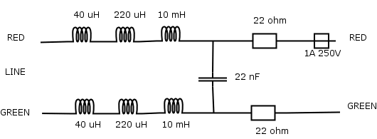
    having had a look at some circuit diagrams of dsl filters on the net, namely this one:
    adsl_filter_circuit.gif
    i think it'll work since there are no one way devices on the line like a diode and the equations i've looked at don't seem to take account of which side is in and which is out, only whether the capacitors and inductors are in series or parallel, which doesn't change when connected the other way (swapping series for parallel makes a high pass filter btw)

    i'm looking at all these LaPlace equations on the net and i can't for the life of me remember how to do them. shows how much use college was :D

    of course, this assumes the filter you have is like the one above


  • Registered Users Posts: 32,417 ✭✭✭✭watty


    That one won't work either way round.

    The 22 Ohms and 22nF will dramtically short out DSL signals if on the line side.

    The 40uH, 220uH and 10mH (capactors missing on schematic?) have a high impedance to the DSL.

    If using a free filter program enter just the top half, and double the capacitor.


  • Registered Users Posts: 21,611 ✭✭✭✭Sam Vimes


    i'm a bit lost by that.
    watty wrote: »
    That one won't work either way round.

    The 22 Ohms and 22nF will dramtically short out DSL signals if on the line side.

    The 40uH, 220uH and 10mH (capactors missing on schematic?) have a high impedance to the DSL.

    are you saying that because of the high frequency of the DSL signal the inductors have a high impedance to it and what stops the signal being killed is the fact that the inductors block the signal from the capacitor and resistors?

    although i don't know why the capacitor and resistors would kill the signal.

    and would i be right in saying that the telephone signal can pass the other way because it's at a lower frequency than the dsl and so the inductors appear to have a lower resistance? why isn't it dramatically shorted out by the capacitor and resistors?
    watty wrote: »
    (capactors missing on schematic?)
    i don't think so, i got the diagram here: http://www.epanorama.net/documents/telecom/adsl_filter.html
    watty wrote: »
    If using a free filter program enter just the top half, and double the capacitor.
    at this i'm completely lost. what filter program? i just got the diagram off the net


  • Moderators, Education Moderators, Home & Garden Moderators Posts: 8,169 Mod ✭✭✭✭Jonathan


    We are all engineers sam... It makes sense in our own heads.

    We cant explain it tho..

    Not even to fellow engineers :P


  • Advertisement
  • Registered Users Posts: 21,611 ✭✭✭✭Sam Vimes


    jmccrohan wrote: »
    We are all engineers sam... It makes sense in our own heads.

    We cant explain it tho..

    Not even to fellow engineers :P

    got it, magic


  • Registered Users Posts: 32,417 ✭✭✭✭watty


    Sam Vimes wrote: »
    i'm a bit lost by that.


    are you saying that because of the high frequency of the DSL signal the inductors have a high impedance to it and what stops the signal being killed is the fact that the inductors block the signal from the capacitor and resistors?

    although i don't know why the capacitor and resistors would kill the signal.

    and would i be right in saying that the telephone signal can pass the other way because it's at a lower frequency than the dsl and so the inductors appear to have a lower resistance? why isn't it dramatically shorted out by the capacitor and resistors?


    i don't think so, i got the diagram here: http://www.epanorama.net/documents/telecom/adsl_filter.html


    at this i'm completely lost. what filter program? i just got the diagram off the net

    I design filters.

    Also there is free software that lets you type in a schematic and plots the response.

    That is an asymetric low pass filter. Only a symetric pi or T filter can work either way round.

    Xc = 1/(2 x pi x freq) (and is always negative)

    Xl = 2 x pi x freq.

    Thus if capacitor is -j x 2411 Ohms at 3kHz (highest phone frequency), it's only 2.45 Ohms at 300KHz (a DSL frequency).

    Since there is 22 Ohm in series, the speech is hardly affected at all, and DSL would be reduced to less than 1/20th of normal.

    10mH is about +j x 188 Ohms at 3kHz. So is about 18800 at 300kHz.

    In simple terms the coils "block" the DSL and pass voice and the capacitor "Blocks" DC and Speech, but shorts out the DSL (higher frequencies.

    And the schematic *IS* missing two smaller value capacitors.


  • Registered Users Posts: 32,417 ✭✭✭✭watty


    So *SOME* filters will work either way round and some won't. It's not the application, but how it was designed.


  • Registered Users Posts: 21,611 ✭✭✭✭Sam Vimes


    watty wrote: »
    I design filters.

    Also there is free software that lets you type in a schematic and plots the response.

    That is an asymetric low pass filter. Only a symetric pi or T filter can work either way round.

    Xc = 1/(2 x pi x freq) (and is always negative)

    Xl = 2 x pi x freq.

    Thus if capacitor is -j x 2411 Ohms at 3kHz (highest phone frequency), it's only 2.45 Ohms at 300KHz (a DSL frequency).

    Since there is 22 Ohm in series, the speech is hardly affected at all, and DSL would be reduced to less than 1/20th of normal.

    10mH is about +j x 188 Ohms at 3kHz. So is about 18800 at 300kHz.

    In simple terms the coils "block" the DSL and pass voice and the capacitor "Blocks" DC and Speech, but shorts out the DSL (higher frequencies.

    And the schematic *IS* missing two smaller value capacitors.

    now you're dredging up some memories. capacitors block DC and low frequencies and inductors block high frequencies. i'm still not sure why it only works one way but i'll take your word for it :)

    you have your answer random.

    /thread lock


  • Closed Accounts Posts: 19,080 ✭✭✭✭Random


    Well thanks for the input lads.


Advertisement