Advertisement
If you have a new account but are having problems posting or verifying your account, please email us on hello@boards.ie for help. Thanks :)
Hello all! Please ensure that you are posting a new thread or question in the appropriate forum. The Feedback forum is overwhelmed with questions that are having to be moved elsewhere. If you need help to verify your account contact hello@boards.ie

animax's alternative dual modding guide

Options
  • 06-05-2010 5:12pm
    #1
    Registered Users Posts: 2,985 ✭✭✭


    I've been meaning to write this guide for a while now, just never got around to it. Its probably a good time now since there will be big buzz around from Super SF4 and this guide can (hopefully) be posted on streetfighter.ie!

    This thread can also act as a place where people can ask for all sorts of info about modding, rather than having to ask on SRK. There are plenty of people here that know a lot about this stuff and will be glad to help.

    First of all, this guide is about alternative methods of dual modding which involve (potentially) no need to solder, although you can solder if you like. There are endless threads on SRK about dual modding using soldering methods so there's no need for me to repeat these methods here. Examples are here, here and here.

    Ever since I modded my hori ex2 and realised that parts of it can be modded without soldering, i've been thinking of ways to mod sticks using similar methods. Some of the methods in this thread are my own ideas which I never bothered to post on SRK to avoid the inevitable flaming (..."why don't you just solder..."), other ideas are well known on SRK. These methods work best on madcatz sticks (SE or TE) since they are designed to be mod friendly but they may also work on other sticks.

    The PS1 pcb method
    Pros:
    • works on ps1 and ps2
    • works on practically every other system using converters (xbox/360/ps3/pc/wii..........)
    • ps1 pads are very easy to padhack
    • will work in practically any stick (hori, madcatz)
    Cons:
    • requires a particular model of ps1 pad
    • poor quality converter may introduce lag
    • inconvenience of swapping converters
    • converter for 360 requires a real wired 360 controller to be connected (once) in order to pass the security check.
    • doesn't make use of the pcb that is currently in the stick so it works best in empty shells or sticks whose pcbs are destroyed

    This is the method that myself and sisko used on our SEs. The playstation 1 pcb is regarded by many as the best pcb there is, partly because it was compatible with the ps2 and now because there are converters for every other system released since! Not only that but some models of the ps1 pcb are amazingly easy to padhack using the spiffyshoes method.

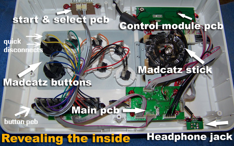
    Once the pad is padhacked using the spiffyshoes method, the next step is to install it into the stick. The beauty of madcatz sticks is that they have already done so much of the "modding" work for you. See the pic below

    100_1204copy.png

    The button pcb marked above is very useful from a modding point of view because it automatically takes the ground wires from each button and combines them into one, meaning that you don't have to daisy chain the ground wire like in other mods.

    The grey ribbon cables coming from the button pcb then carries the signal of each button (including start and select), along with the (now) common ground to the main pcb. And it even tells you on the button pcb which grey wire corresponds with which button!

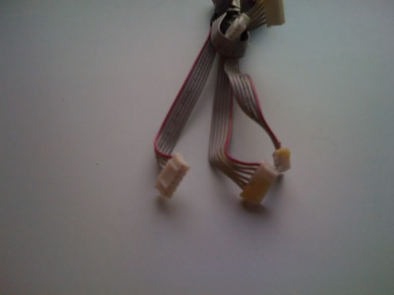
    So all you need to do to connect these buttons to the ps1 pcb is to connect the wires coming from the ps1 padhack (the wires sticking out from the spiffyshoes padhack) to the relevant wire of the grey ribbon cable, which looks like this below

    IMG_0193.jpg

    There are a number of ways to connect these wires:

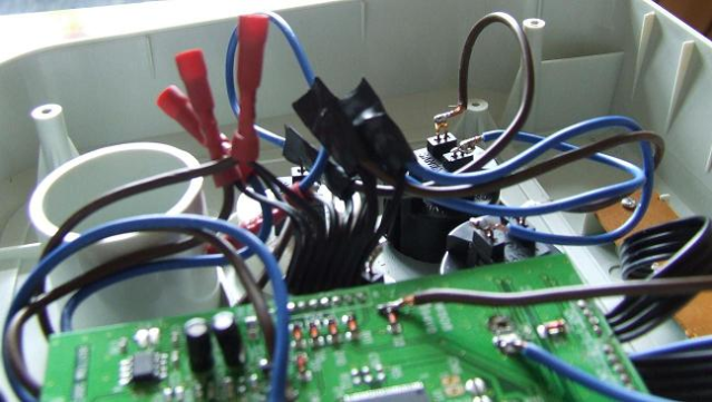
    You could cut away the plastic end of the ribbon cable to reveal the individual wires and then join them to the relevant wires form the pad by simply twisting (splicing) them together and insulating them (with insulating tape or crimp terminals). This is similar to what i did in my hori mod below.

    solderlessFix.png

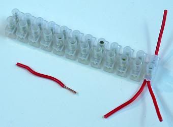
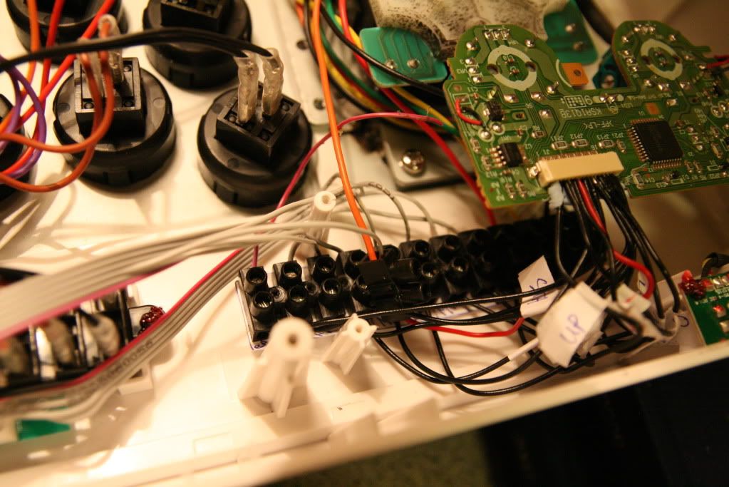
    Even easier, you could just join them using terminal blocks (like in the next pic below)

    Or you could simply insert the cables from the padhack directly into the white plastic end of the ribbon cable. This is what i did for my SE mod but unfortunately i don't have pictures yet. Insulate and secure the connections with insulating tape.

    Alternatively you could use some of the cool techniques explained in this video.

    Similar techniques apply to the directional inputs from the stick, you just have to connect the up/down/left/right from the padhack to the relevant wires of the ribbon cable coming from the stick.

    Note: the only remaining issue is with the ground cable from the stick. This has to join with the ground cable coming from the button pcb before joining with the ground wire coming from the padhack. The easiest way to do this is to use a terminal block with two wires in one end and one wire in the other. Like in this pic

    euro.jpg

    Once that is done, eveything is ready!! Note that we have not wired up the home/guide button. This is because the converters for ps3 and 360 have home/guide buttons built into them.

    The Datel/Joytron Paewang method
    Pros:
    • the smallest and most efficient dual mod pcb
    • ps3 and 360 compatibility out of the box
    • very inexpensive
    • will fit in any stick

    Cons:
    • it is unofficial and has a way around microsoft controller security. This could be blocked by microsoft with an update, but unlikely

    This is the mod that I am currently in the middle of (just waiting to get a stick to put it in!). These pcbs can be bought separately or for the same price, inside a stick. Datel have an identical stick with the same pcb. I bought this one for 40 euro delivered! I would recommend getting the stick since it is the same price and the pcb inside the stick is easier to connect to than the ones bought separatelty.

    This is what it looks like on the inside

    sv102452.jpg

    The great thing about this is that the brown button board can be removed completely to reveal little metal prongs as seen below

    pinsclose.jpg

    What I plan to do is to connect the buttons of a TE to these little prongs simply using the grey ribbon cable connectors that are already in the TE (or SE). i.e. the ones in this pic

    IMG_0193.jpg

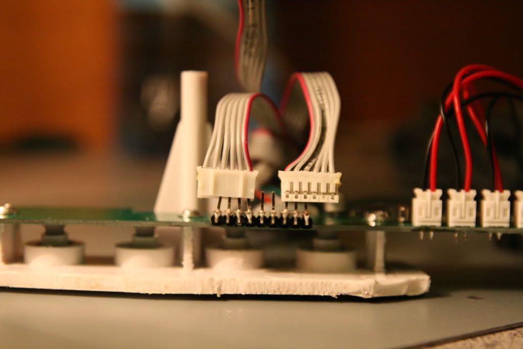
    Amazingly, the white plastic heads of the ribbon cable in the TE with fit directly onto the metal prongs of the datel pcb, joining the connections. They just have to be arranged in the right order so that the ground cable connects to the ground prong. This deals with the main buttons.

    As for the directionals, some people have used quick disconnects to connect to the white plastic enclosures on the pcb itself like in this pic

    100_0556-1.jpg

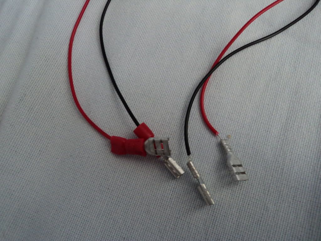
    I think its a better idea to leave the original red/black cables in place and just put quick disconnects on the end of those, like in this pic

    DSC00038.jpg

    The last remaining issue is the start/select/turbo/guide buttons and how to connect them to a TE or SE. On the face of it, it seems as though you have to solder to the points marked under the pcb in the pic below

    paewang_revolution_pcb.jpg

    Instead I might actually get really ghetto on this one! I've cut away the top panel of the Datel case, keeping the start/select/guide/turbo buttons intact, still connected to the pcb. I can then place this top panel in the turbo panel of the TE like in the first pic below, or else have it hidden in the wire compartment as in the second pic below. This means that i wouldn't have to rewire those buttons.

    TEwithpanel.png

    or alternatively

    TEcompartment.png

    I will update with more pics once i finally get to do this mod.

    The Dual Strike method
    Pros:
    • very easy to implement
    • great pcb with regular firmware updates
    • has a ribbon cable connector for 360 piggyback
    • inexpensive

    Cons:
    • works best on a 360 TE or 360 SE, not so useful for ps3 sticks

    If I had one choice, this is the mod that I would go for. The thread is on SRK with all the info needed and a great tutorial is written here. Even though the guide uses soldering techniques, it can be done without soldering using the same sort of ideas that i've mentioned in this post. I haven't tested it but my belief is that it can be done.

    If i had a 360 TE (and hadn't already bought a Datel pcb!) I would definitely go with this method.

    The TEasy mod method
    Pros:
    • newest method, and probably the easiest!

    Cons:
    • Works only on 360 TE and SE sticks (round 1)
    • still only in testing phase

    This is a brand new method, posted only a few days ago on SRK. It is an ingenious idea. It literally piggybacks the 360 pcb by sitting on its back :P

    It can then interface with a ps3 pcb such as a Dual Strike. This is also a great method but is not available yet. Worth keeping an eye on.

    Thats about it for now. Unfortunately I won't be able to edit this post much longer so newer comments and suggestions might appear later in the thread.


Comments

  • Registered Users Posts: 14,181 ✭✭✭✭Jim


    n1 Terry. I'll throw this on the site later.


  • Registered Users Posts: 2,910 ✭✭✭Sisko


    Fair play terry! I'll be uploading pics of the inside of my stick soon enough to the modded stick thread. You'll probably have no use for them but if you do your more then welcome to use 'em.

    Even as a 'what not to do' pic hahahaha


    But fair play man , really good right up. Deffo post it on SRK as well.


    It'd be sweet it if a mod could post this thread under the sticks and parts section of this sticky thread : http://boards.ie/vbulletin/showthread.php?t=2055554590


    Also just to say :
    animaX wrote: »
    The PS1 pcb method
    Pros:

    * works on ps1 and ps2
    * works on practically every other system using converters (xbox/360/ps3/pc/wii..........)
    * ps1 pads are very easy to padhack
    * will work in practically any stick (hori, madcatz)

    Cons:

    * requires a particular model of ps1 pad
    * poor quality converter may introduce lag
    * inconvenience of swapping converters
    * converter for 360 requires a real wired 360 controller to be connected (once) in order to pass the security check.
    * doesn't make use of the pcb that is currently in the stick so it works best in empty shells or sticks whose pcbs are destroyed

    For the pros I guess you could add that its potentially solderless too. And that last con that I highlighted, couldn't that be seen as a pro? Worked great for me since it meant I could use Barrys shell.


  • Registered Users Posts: 2,985 ✭✭✭animaX


    Thanks sisko. I could definitely use some pics from inside the ps1 mod. The only camera I have is the crappy iphone camera so I can't do good shots. Maybe post your worklog on this thread as well as the custom/modded sticks thread?

    It would be nice to have a successfully completed example of the method in this thread too

    Edit: yeah thats true about the pros and cons. It was definitely a pro for me too since a got a shell from bush but most people would have a working pcb and will wonder why its being wasted! In that case they would probably be better off going for an alternative (dual strike) method.


  • Registered Users Posts: 18,707 ✭✭✭✭K.O.Kiki


    Gah, I am now, once again, not top dog anymore.
    Darn you Terry! ;)


  • Registered Users Posts: 2,985 ✭✭✭animaX


    K.O.Kiki wrote: »
    Gah, I am now, once again, not top dog anymore.
    Darn you Terry! ;)

    Haha, i didn't mean it that way. Its different for you because you can actually solder! You can do the conventional dual mods. This guide is for twats like me who like to avoid soldering at all costs :P


  • Advertisement
  • Registered Users Posts: 2,910 ✭✭✭Sisko


    animaX wrote: »

    The PS1 pcb method
    This is what i did for my SE mod but unfortunately i don't have pictures yet.


    Heres a pic of mine.


    inside.jpg


  • Registered Users Posts: 220 ✭✭meducation


    savage thread man gonna try some of these for my dual mod


  • Registered Users Posts: 2,985 ✭✭✭animaX


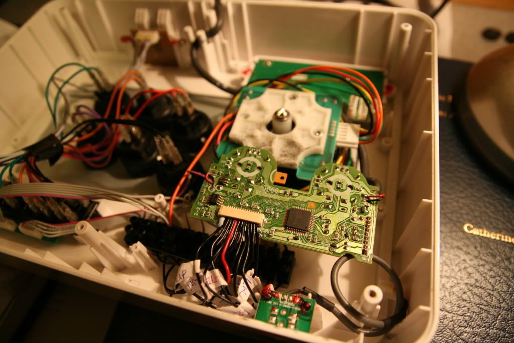
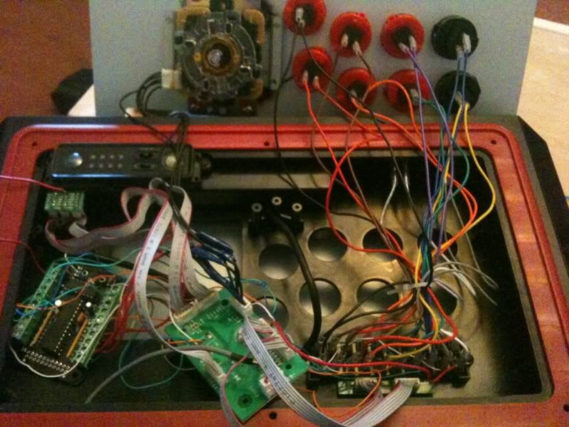
    Right, i finally got my hands on a good camera so i took some shots of the inside of the ps1 pad stick. It wasn't so neat to begin with so i rewired it again to tidy it up.

    IMG_4094.jpg

    Used a terminal block to keep things organised. I also cut and separated the wires from the grey ribbon cable, giving a more secure connection.

    IMG_4097.jpg

    Bonus: here is a pic of the datel pcb ready to be inserted into a TE. The grey ribbon connectors fit directly onto the prongs (with a bit of bending) and are held in place with the tension of the prongs.

    IMG_4098.jpg


  • Registered Users Posts: 2,910 ✭✭✭Sisko


    Impressive Terry, I was gonna buy a block of those things (thermal block its called?) but I never even considered keeping them connected , always saw myself breaking them off and using them one by one, basically was thinking about keeping the wires secure rather then neatness also.

    So I might try that myself when I buy one of those yokes.

    At the moment I'm making sure I've spare pieces of electric tape stuck on the inside of my case, and a screwdriver with me at all times, for those times a wire comes loose.


  • Registered Users Posts: 2,985 ✭✭✭animaX


    Thanks man, and they're called terminal blocks or terminal strips. They are very useful for neatness alright.

    My wires are pretty solid now, i'd be surprised if they came loose. I haven't managed to do it yet but if I push the pcb a bit closer to the edge of the case i'll be able to screw it in place using the screw that originally held the pcb into the ps1 pad shell.


  • Advertisement
  • Registered Users Posts: 18,707 ✭✭✭✭K.O.Kiki


    I've loads of terminal strips if you want any.


  • Registered Users Posts: 2,910 ✭✭✭Sisko


    Hell yes


  • Registered Users Posts: 2,985 ✭✭✭animaX


    Edit: Nevermind, i thought my TEasy board had arrived in the post but it turns out it was something else. The word rage doesn't begin to cover it!

    On a related note, BanjoB recently dual modded his TE using a chimp. He sent me this pic
    IMG_6807.jpg


  • Registered Users Posts: 531 ✭✭✭BanjoB


    animaX wrote: »
    Edit: Nevermind, i thought my TEasy board had arrived in the post but it turns out it was something else. The word rage doesn't begin to cover it!

    On a related note, BanjoB recently dual modded his TE using a chimp. He sent me this pic
    IMG_6807.jpg

    That was the untidy finished job. I screwed the chimp (board on the left) to the bottom casing and used ties for the wiring. Much tidier now.

    I'm very happy with the job. If anyone has any questions, feel free to ask. Involved some soldering but used a solderless method for the buttons.


  • Registered Users Posts: 531 ✭✭✭BanjoB


    Did they send the wrong board Terry???.


  • Registered Users Posts: 2,985 ✭✭✭animaX


    BanjoB wrote: »
    That was the untidy finished job. I screwed the chimp (board on the left) to the bottom casing and used ties for the wiring. Much tidier now.

    Post pics if you can, don't be shy!
    BanjoB wrote: »
    Did they send the wrong board Terry???.

    Nah, i got an email from one of the lads in the office saying there was a package on my desk for me. The only thing i'm waiting on is the TEasy. So i ran into the office like a giddy child but it turns out the secretary had just gave me back something i had loaned to her the week before :(

    I can't describe how raging i was. It should come next week though. Will defo have it done in time for the next inferno (probably even the week before that)


  • Registered Users Posts: 2,910 ✭✭✭Sisko


    Your a gas many terry. A gas man.


  • Registered Users Posts: 322 ✭✭Robbknoll


    Hey guys, hope this is in the right place, ive a TE myself and im having problems with the stick. It feels like its gotten a bit sluggish and unresponsive (where inputs are concerned). Its been through the wars a bit but it always seemed grand so this is a recent thing. Im wondering if ill need a new part or if theres something i can do to fix it myself. Ive opened it and had a look in but tbh i dont know what im looking at, everything seemed ok to me..

    Any help is appreciated :)


  • Moderators, Music Moderators Posts: 25,868 Mod ✭✭✭✭Doctor DooM


    Robbknoll wrote: »
    Hey guys, hope this is in the right place, ive a TE myself and im having problems with the stick. It feels like its gotten a bit sluggish and unresponsive (where inputs are concerned). Its been through the wars a bit but it always seemed grand so this is a recent thing. Im wondering if ill need a new part or if theres something i can do to fix it myself. Ive opened it and had a look in but tbh i dont know what im looking at, everything seemed ok to me..

    Any help is appreciated :)

    Check the little switch on the top left is set to "dp" note l or rs. :)


  • Registered Users Posts: 1,206 ✭✭✭unky chop chop


    Have a looksy at the spring.Could well be that. Take it out( you have to take eclip off) and give it a good stretch. Maybe you need a new spring or at worst new microchip board..


  • Advertisement
  • Registered Users Posts: 1,206 ✭✭✭unky chop chop


    Check the little switch on the top left is set to "dp" note l or rs. :)

    Ya know I switched this the other week by mistake and went mad thinking I had lost all skill, timing and muscle memory in Street fighter all together.
    Little bugger of a thing


  • Registered Users Posts: 2,985 ✭✭✭animaX


    Yeah it might be what doom suggested. If it's set to analogue then the inputs "go on" for longer than they should, rather than being a precise input.

    If the stick is getting looser then it would be the spring issue as unky suggested.


  • Registered Users Posts: 322 ✭✭Robbknoll


    Check the little switch on the top left is set to "dp" note l or rs. :)

    Through trial and error i found out about that switch and which one to keep it on so im thinkin its not that cos i check it if i feel the TE feels odd. Ill keep a close eye on it tho just incase i am switching it by accident.

    Also ill have a crack at stretching the spring, altho i dont think id be cinfident enough to do it right haha.

    Stupid question, but what is the functions of the 3 settings?


  • Registered Users Posts: 11,005 ✭✭✭✭chopperbyrne


    Robbknoll wrote: »
    Stupid question, but what is the functions of the 3 settings?

    Left Stick, Right Stick and D-pad.


  • Registered Users Posts: 2,985 ✭✭✭animaX


    Ok so i finally did my dual mod a few weeks ago using the TEasy board!! I was waiting till after inferno to write up about it so i'll do it now.

    Thankfully, i was one of the few people who managed to get their hands on the first batch of TEasy boards. They were being sold at EVO (i asked Azza to get me one but he couldn't find the seller!) and fortunately there were a few left over from EVO which he sold on a first-come, first-serve basis. There might be a few left for TE S (super) sticks but not for the original TE.

    DSC00356.jpg

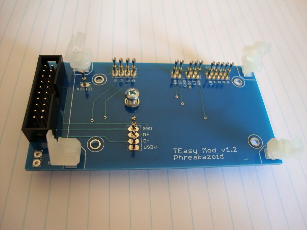
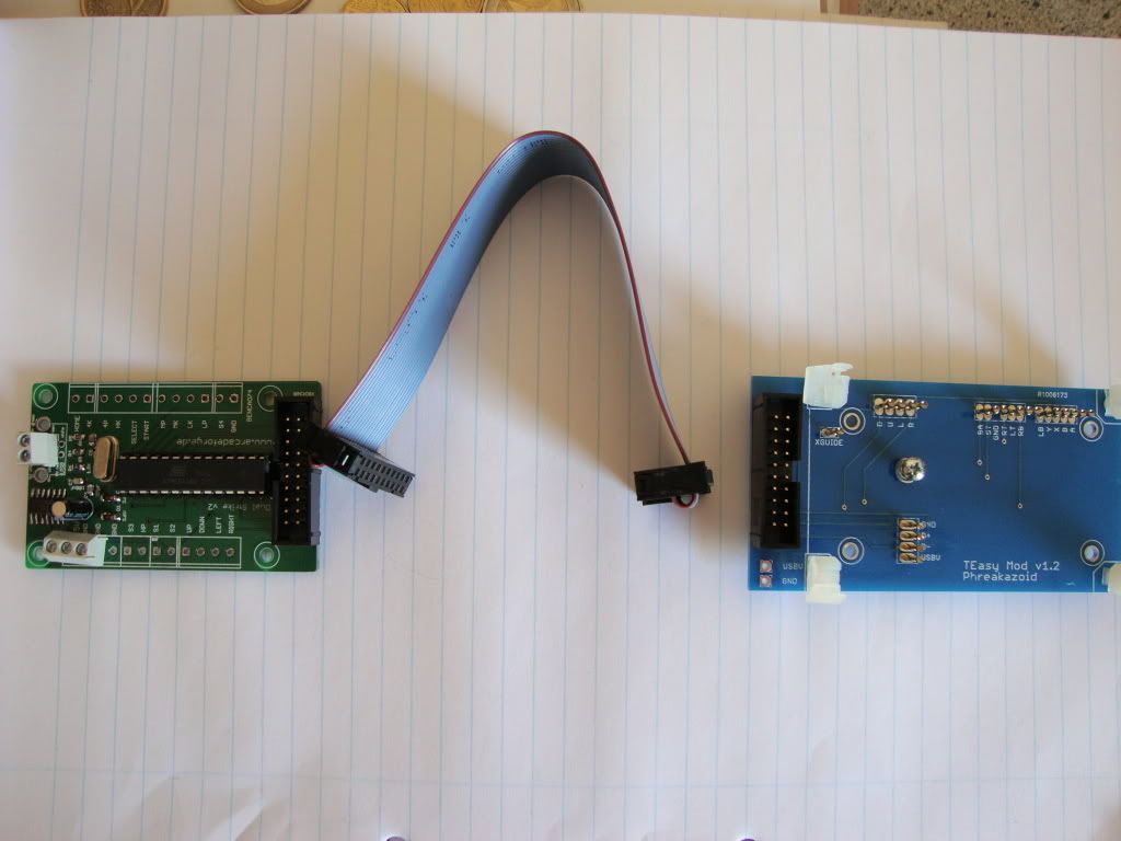
    The board itself is genius. It contains no components whatsoever, just spring-loaded cups which the underneath of the TE pcb sits on, and then copper tracks to take the hijacked signals to the ribbon connector.

    The ribbon cable comes supplied with the board and attaches to a Dual Strike pcb as seen in the pic below

    DSC00358.jpg

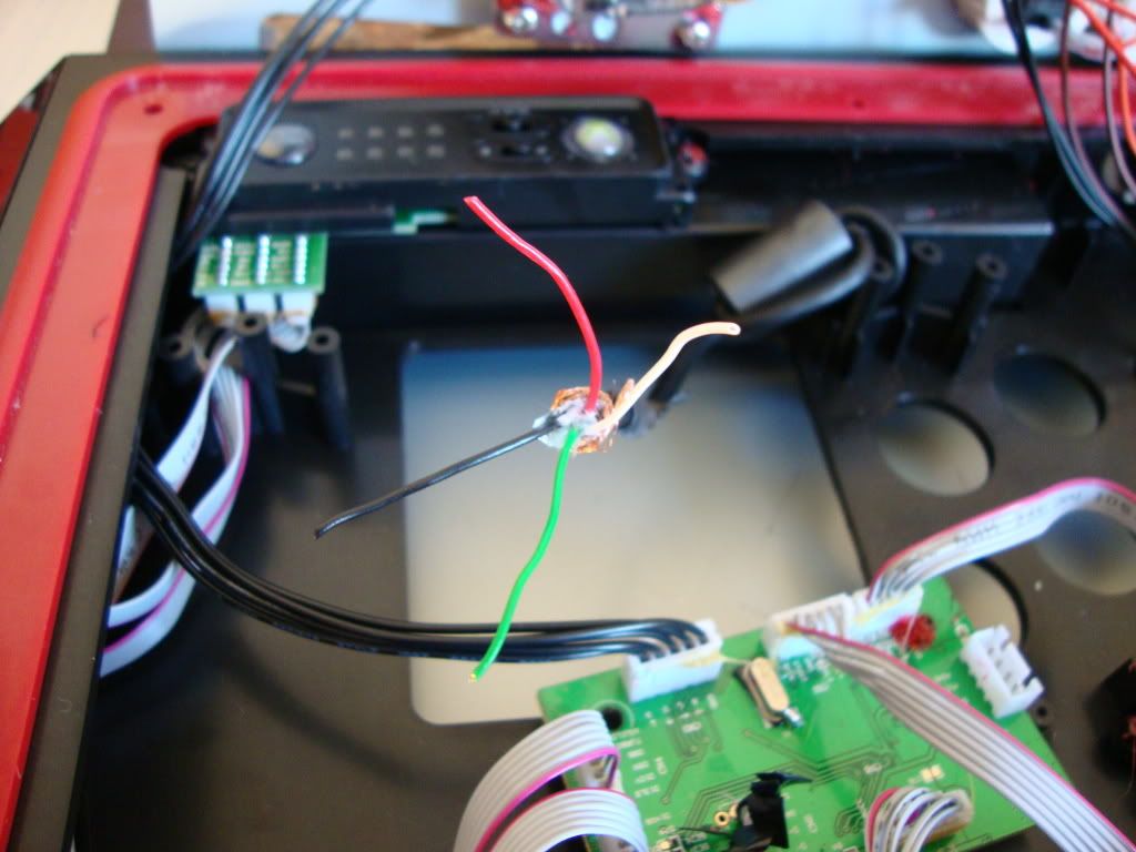
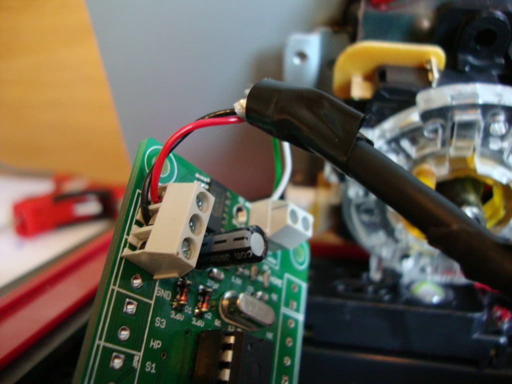
    The scariest part of the whole mod is disconnecting the usb cable from the original TE pcb. This is the point of no return!! (well, there is a return if you solder them back onto the spots). The individual strands of the usb cable also have to be stripped back a little.

    DSC00359.jpg

    You then sit the TEasy board on the spot where the original pcb was, and screw it down using the screws that originally held the TE pcb in place.

    DSC00360.jpg

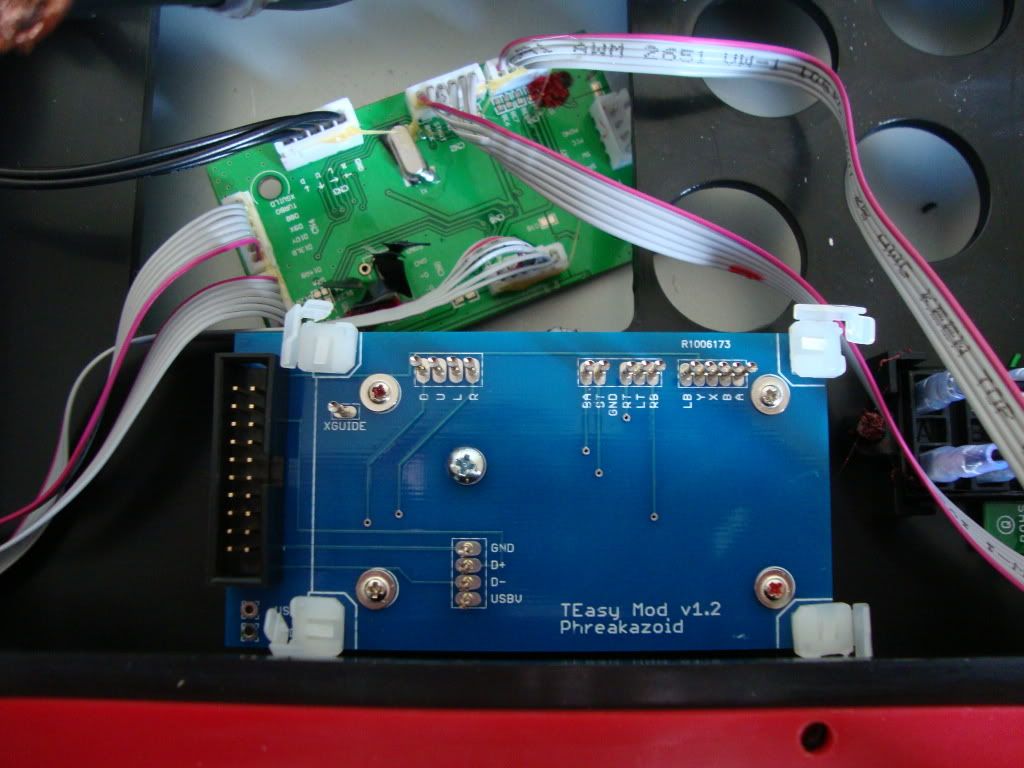
    The next step is to carefully sit the original pcb on top of the TEasy board ensuring that the underside of the solder joints sit exactly in the spring-loaded cups. The original pcb is held firmly in place using the white clips at the edge of the TEasy board. This step was trickier than i expected. It is recommended to slightly trim the underside of the solder joints on the original pcb since they are pretty sharp. By trimming them with a clipper they will fit better in the spring-loaded cups. Here is a pic of the TE pcb sitting on top of the TEasy

    DSC00361.jpg

    The last step is to re-attach the usb cable to the Dual Strike pcb. After a recommendation from none other than myself, the guy who designed the Dual Strike created a new version of the Dual Strike which now has screw terminals to re-attach the usb cable (originally it had a usb B connector so you had to create a usb B connection from the old usb cable and plug in it to the Dual Strike).

    DSC00362.jpg

    The mod didn't go off without a hitch though. When i tried it first it didn't work! After a few days of head-scratching i discovered that I hadn't attached the usb cable to the Dual Strike securely enough. Thankfully, after the initial teething problems it now seems to be working very well (though I haven't tested enough on ps3).

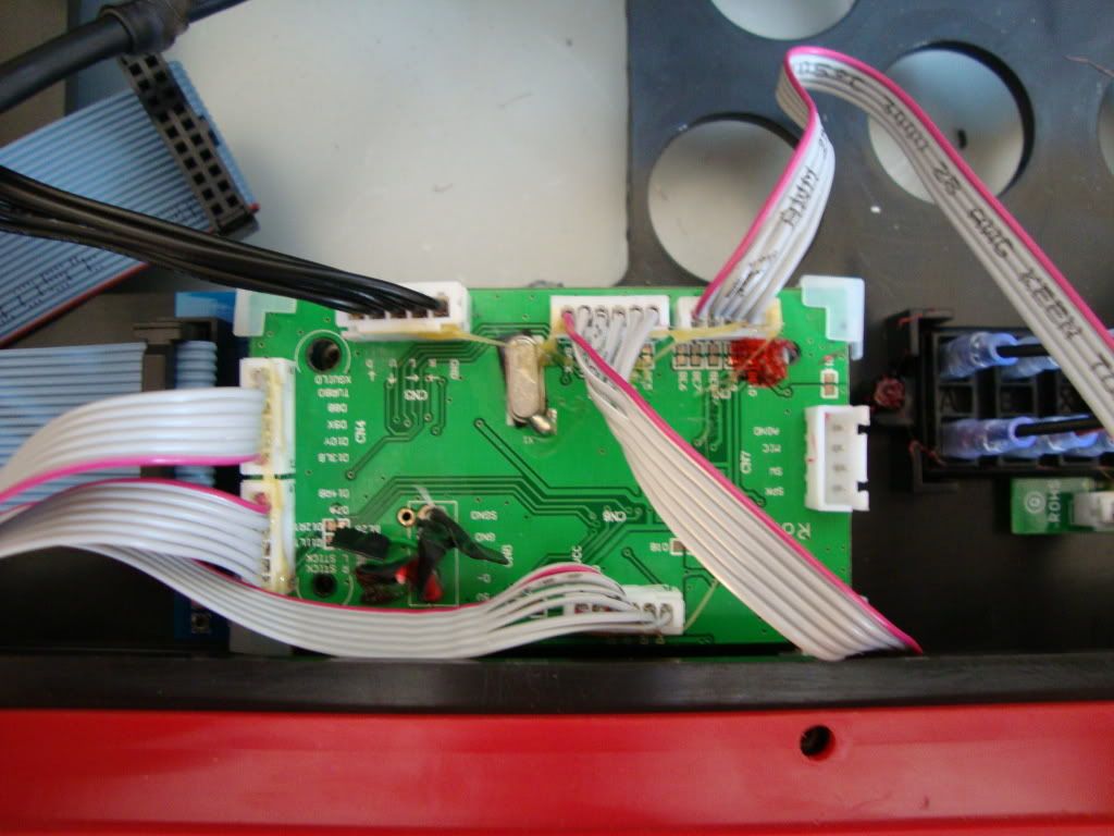
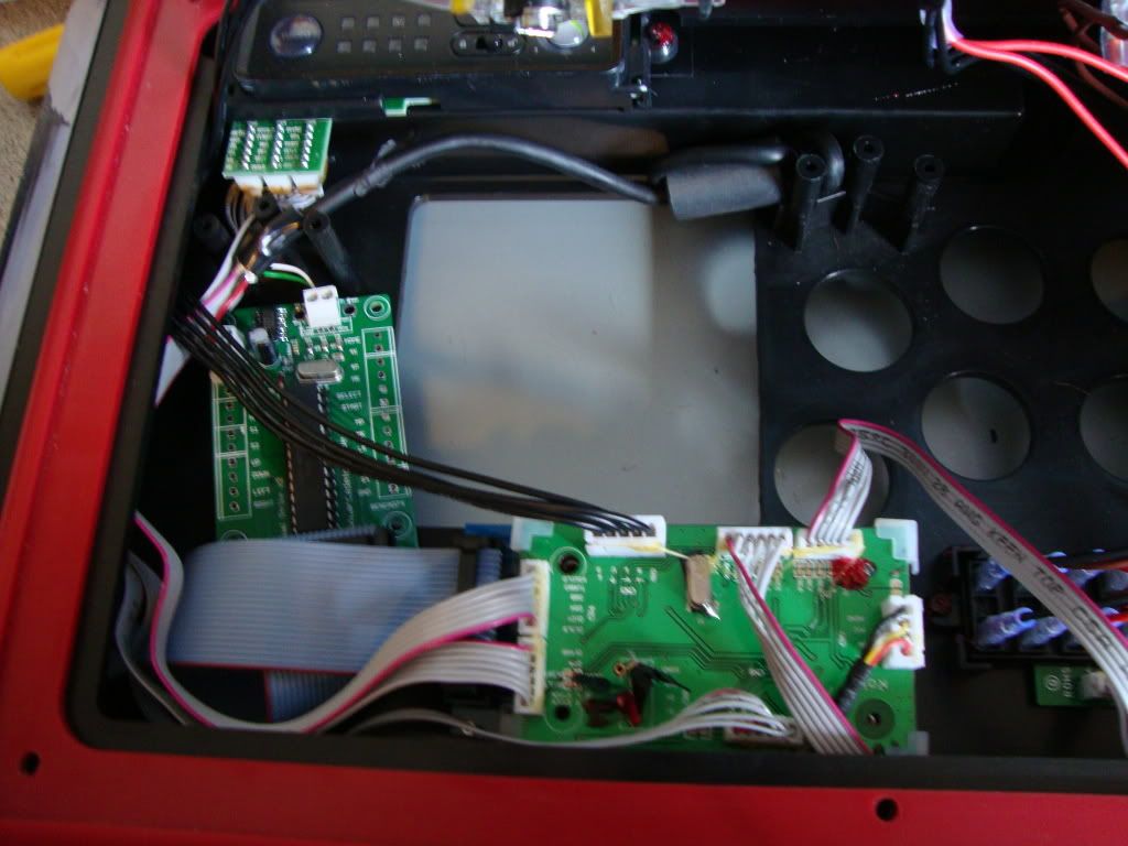
    Here is the final image from inside:

    DSC00363.jpg

    It runs as follows: If i plug the stick into a device without holding any button, the usb signal goes to the Dual Strike and the Dual Strike takes the button and direction signals from the ribbon cable. If i hold any punch or kick button while plugging the stick in, the usb signal goes through the Dual Strike to the original pcb and then it runs as normal. (i can also change this by default in the configuration mode so that the signal goes to original pcb without pressing anything).

    And that's it!! I would recommend this mod to anyone interested but I would wait a bit longer because the two lads who make the TEasy and Dual Strike are working on a 2-in-1 board which will do it all :cool:


Advertisement