Advertisement
If you have a new account but are having problems posting or verifying your account, please email us on hello@boards.ie for help. Thanks :)
Hello all! Please ensure that you are posting a new thread or question in the appropriate forum. The Feedback forum is overwhelmed with questions that are having to be moved elsewhere. If you need help to verify your account contact hello@boards.ie

Boiler control 3 Channel time clock

Options
  • 27-10-2010 5:29pm
    #1
    Registered Users Posts: 352 ✭✭


    I was looking at the circuit diagram found here

    I'm wondering would there be a problem wiring like this...

    I said it to a qualified sparks, and he mentioned something about back feed, but I'm not quite sure what he was getting at.
    boiler1.png


Comments

  • Registered Users Posts: 76 ✭✭086lavey


    With that diagram , you would be fine , as long as your using a 3 channal clock , when you start using single channel clocks apt flash etc , your going to get back feeds on the valve contacts , (ie) clock light staying on when clock is off ,while using the other single channel clocks,


  • Registered Users Posts: 352 ✭✭Egyptian


    086lavey wrote: »
    With that diagram , you would be fine , as long as your using a 3 channal clock , when you start using single channel clocks apt flash etc , your going to get back feeds on the valve contacts , (ie) clock light staying on when clock is off ,while using the other single channel clocks,

    What if the timeclock has one Live In, and three Live Out... one for each channel?

    What exactly is happening when backfeed occurs? And is there a wiring fix?


  • Closed Accounts Posts: 13,422 ✭✭✭✭Bruthal


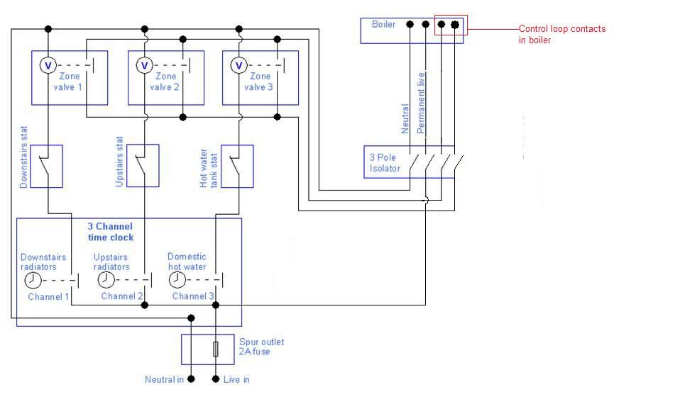
    Is it an oil boiler or gas? A gas boiler should have a control loop so you dont need to connect one side of the valve contacts to the stats output, you just connect one terminal of control loop to one side of all 3 valve contacts, and the other control loop termanal to the other 3 valve contacts.

    But even if you do use a live feed into the valve contacts, this can be a single feed from the spur fuse straight to the 3 valve contacts connected together instead of individual feeds trom stats as in diagram, and the other side of all 3 contacts connected together and on to the boiler.

    Update
    Actually i have just looked at the diagram you linked to OP. This diagram shows what i mentioned about a single feed from the spur fuse feeding all 3 valve contacts. Thats the way i would do it if there is no control loop terminals in the boiler, but there usually is in the gas boilers.
    And the above diagram will disconnect the supply from a gas boiler as soon as the last timer or stat opens and wont allow boiler pump run on, which is needed to circulate the water from the hot exchanger for a few minutes after the boiler stops heating.
    If its an oil boiler it might be ok. But its always better for the water to circulate for a couple of minutes after heating goes off.


  • Registered Users Posts: 352 ✭✭Egyptian


    And the above diagram will disconnect the supply from a gas boiler as soon as the last timer or stat opens and wont allow boiler pump run on, which is needed to circulate the water from the hot exchanger for a few minutes after the boiler stops heating.

    Many thanks for the info. Is there a wiring solution? or do you need to fit another timer on the valve itself?


    is there any possibility the valves could be energised when they're not supposed to be?


  • Closed Accounts Posts: 13,422 ✭✭✭✭Bruthal


    Egyptian wrote: »
    is there any possibility the valves could be energised when they're not supposed to be?

    It is possible actually that your electrician is right, when for example the downstairs radiators stat opens, the downstairs valve should now close, but it wont, it will be feeding itself through its own contact, that valve will stay on, so the circuit you linked to is what you should use, not the one you have in your original post, so do it with a feed from the spur fuse feeding all 3 valve contacts. Or the boiler control loop terminals connected to the valve contacts, one terminal to one side of all 3 valves
    The diagram in your original post will backfeed alright.


  • Advertisement
  • Closed Accounts Posts: 13,422 ✭✭✭✭Bruthal


    Egyptian wrote: »
    Many thanks for the info. Is there a wiring solution? or do you need to fit another timer on the valve itself?


    is there any possibility the valves could be energised when they're not supposed to be?

    The diagram you linked to in your first post is the way to do it, not the diagram actually in your first post. That will not work.

    But as i said, if its a gas boiler it will have a control loop, but you still have not said if its a gas boiler.


  • Closed Accounts Posts: 4,431 ✭✭✭M cebee


    how many diagrams are there


  • Closed Accounts Posts: 13,422 ✭✭✭✭Bruthal


    M cebee wrote: »
    how many diagrams are there

    He has a diagram in his first post which he said his electrician said will backfeed, and he is right, it will, that diagram wont work

    Then he has a link to a diagram posted by fishdog last year, that will work, and then there is almost the same one as fishdog`s one but you just use the valve contacts connected to the boiler control loop which is the proper way to do it with modern gas boilers. A live comes from the boiler to the valve contacts in parallel, and from the other side of valve contacts in parallel back to the boiler switched live terminal. So any boiler safety features will now be incorporated into the valve contacts loop.


  • Closed Accounts Posts: 4,431 ✭✭✭M cebee


    robbie7730 wrote: »
    He has a diagram in his first post which he said his electrician said will backfeed, and he is right, it will, that diagram wont work

    Then he has a link to a diagram posted by fishdog last year, that will work, and then there is almost the same one as fishdog`s one but you just use the valve contacts connected to the boiler control loop which is the proper way to do it with modern gas boilers. A live comes from the boiler to the valve contacts in parallel, and from the other side of valve contacts in parallel back to the boiler switched live terminal. So any boiler safety features will now be incorporated into the valve contacts loop.

    ah ok i can't see it-must be the browser
    i'll delete my post so if it's incorrect- i was looking at the link


  • Closed Accounts Posts: 13,422 ✭✭✭✭Bruthal


    M cebee wrote: »
    ah ok i can't see it-must be the browser
    i'll delete my post so if it's incorrect- i was looking at the link

    Yea i was just about to suggest maybe you could not see his diagram as you were havin trouble the other day with that.


  • Advertisement
  • Closed Accounts Posts: 13,422 ✭✭✭✭Bruthal


    Egyptian wrote: »
    boiler1.png

    Can you see it here now mceebe?


  • Closed Accounts Posts: 4,431 ✭✭✭M cebee


    no nevermind i'll sort it out soon


  • Registered Users Posts: 352 ✭✭Egyptian


    M cebee wrote: »
    how many diagrams are there

    There's 2. One I found on boards, and one I designed but is flawed.


    Apologies, it's an oil boiler


  • Closed Accounts Posts: 13,422 ✭✭✭✭Bruthal


    Egyptian here is the diagram using control loop in boiler if there is one, i modified this from
    the one you linked to in your first post.

    boilercontroldiagram.jpg

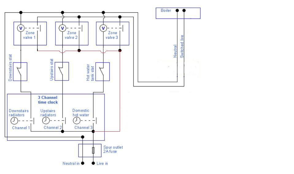
    If there is not a control loop you use the diagram you linked to in your first post, not the diagram you have actually in your first post.


  • Closed Accounts Posts: 13,422 ✭✭✭✭Bruthal


    Egyptian wrote: »
    There's 2. One I found on boards, and one I designed but is flawed.


    Apologies, it's an oil boiler

    Here is your one modified slightly so there will be no back feed problems and should work on an oil boiler. It can bring on the boiler and the circulating pump. I would put a pipe stat feeding the pump to keep it running a few minutes after the boiler shuts off.
    boilercontroldiagram2.jpg


  • Registered Users Posts: 352 ✭✭Egyptian


    robbie7730 wrote: »
    Egyptian here is the diagram using control loop in boiler if there is one, i modified this from
    the one you linked to in your first post.

    If there is not a control loop you use the diagram you linked to in your first post, not the diagram you have actually in your first post.

    That's great.

    Out of curiosity, if for instance the Downstairs and Upstairs Channels were on, and the Upstairs stat opened, would the current energising the valve via backfeed travel the red or blue path? Is it being fed from the Neutral?

    boiler2.png


  • Closed Accounts Posts: 13,422 ✭✭✭✭Bruthal


    It will feed through the downstairs zone valve contact from the live through the upstairs still closed contact into the upstairs zone valve motor, so not allowing to upstairs valve to de energise, so its contacts stay closed and water continues to flow.

    In effect once 2 valves or more are energised and their contacts are closed, their motors are being fed from 2 places at once. So if the stat or timer opens, they are still fed through their own contact in this circuit. So the motors will stay energised.


  • Registered Users Posts: 352 ✭✭Egyptian


    robbie7730 wrote: »
    It will feed through the downstairs zone valve contact from the live through the upstairs still closed contact into the upstairs zone valve motor, so not allowing to upstairs valve to de energise, so its contacts stay closed and water continues to flow.

    In effect once 2 valves or more are energised and their contacts are closed, their motors are being fed from 2 places at once. So if the stat or timer opens, they are still fed through their own contact in this circuit. So the motors will stay energised.

    I get you now, if one stat cuts out while there's another valve open, the valve that should close now has an alternate source of power, and stays open. So you end up heating the whole house when only the downstairs should be on.

    Thanks for all your information Robbie, much appreciated.


  • Closed Accounts Posts: 13,422 ✭✭✭✭Bruthal


    Egyptian wrote: »
    I get you now, if one stat cuts out while there's another valve open, the valve that should close now has an alternate source of power, and stays open. So you end up heating the whole house when only the downstairs should be on.

    Yes now you have it, thats exactly it,


Advertisement