Advertisement
If you have a new account but are having problems posting or verifying your account, please email us on hello@boards.ie for help. Thanks :)
Hello all! Please ensure that you are posting a new thread or question in the appropriate forum. The Feedback forum is overwhelmed with questions that are having to be moved elsewhere. If you need help to verify your account contact hello@boards.ie

Krugmann wireless stats and motorised valves

Options
  • 11-12-2010 12:04am
    #1
    Registered Users Posts: 1,519 ✭✭✭


    ok decided to take advantage of the motorised valves that are in my house which has been un-used up until now,i have a 70/90 heatpac firebird boiler.

    I decided to get these stats which are also timeclocks
    i have 2 of these for upstairs and downstairs
    http://www.rvr.ie/Products/SEC960/0_292_47_294_296_269/

    and 1 of these for hot water
    http://www.rvr.ie/Products/SEC962/0_292_47_294_296_269/

    there isnt any detailed drawings for wiring to motorised valves
    the motorised valves are 5 core,brown,blue,earth,grey and orange

    what way should they be wire so i can use the stats to controls the zones as intended and call for heat and switch on the boiler as required?thanks in advance
    [IMG]file:///C:/Users/Colin/AppData/Local/Temp/moz-screenshot-1.png[/IMG]


    i would be thinking that the wire from the receivers would go to the browns of the motorised valves and that either the orange or the grey would go back to the boiler in parallel from each valve but then i would have a wire left over so just looking for clarification


Comments

  • Closed Accounts Posts: 13,422 ✭✭✭✭Bruthal


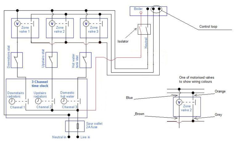
    Here is a diagram, its in the sticky section in this forum but i modified it a bit for using on a boiler where you remove the link in the control panel terminals. Its usually a link in terminals beside the Main Live, Neutral and Earth terminals into boiler. A seperate view of one motorised valve shows the brown blue orange and grey wires. Brown and blue are Live and Neutral to power the motor in the valve. Orange and grey are the contacts which open and close. So once any motor valve is powered on by a stat and the timeclock then it opens to allow water flow, and also closes the contact between orange and grey to fire up the boiler.

    boilercontrolcircuit-1.jpg


  • Closed Accounts Posts: 13,422 ✭✭✭✭Bruthal


    glic83 wrote: »
    i would be thinking that the wire from the receivers would go to the browns of the motorised valves and that either the orange or the grey would go back to the boiler in parallel from each valve but then i would have a wire left over so just looking for clarification

    Yes the receiver would power each motorised valve instead of the hard wiring in the diagram above. So each stat which has its own timer would just bring on each individual motorised valve its controlling, so the timer in the above diagram is also not needed. The main thing is the motorised valve contacts. Check the boiler has a removable control link, and then the orange and greys can all be connected in parallel as in diagram to connect where the control link was in boiler. So any one or more valves opening will close the grey/orange contact and so closes the control loop and boiler comes on.


  • Registered Users Posts: 1,519 ✭✭✭glic83


    think i have it does the orange from the motorised valve need a permanent live then?


  • Closed Accounts Posts: 13,422 ✭✭✭✭Bruthal


    glic83 wrote: »
    think i have it does the orange from the motorised valve need a permanent live then?


    Well on a boiler with the control loop the live to the motorised valve contacts is on one of the control loop terminals in the boiler. But it looks like you have an oil fired boiler so that may not have a control loop, in which case you would connect Live to all 3 oranges, and then all 3 greys would be the switched live into the boiler to run it, not sure if that boiler has a pump over run facility in it. This allows the pump to continue running after the boiler goes off when all motor valves are closed to continue circulating the water to dissipate heat from the boiler.


  • Registered Users Posts: 1,519 ✭✭✭glic83


    its an oil boiler m8 have it all working away i might put a by pass between the flow and return on the boiler to help disioate the heat from the boiler cheers for your help


  • Advertisement
  • Closed Accounts Posts: 13,422 ✭✭✭✭Bruthal


    what controls it at the moment? Does it continue running after the stat or timeclock goes off at present? If not then it probably does not need to run on and so then just the live feed to the 3 valve switches (oranges) then 3 greys connected together then go to power the boiler. Orange or grey polarity does not matter.


  • Registered Users Posts: 1,519 ✭✭✭glic83


    thats the way i have it wired at the moment out of the receiver and connected to the browns of the mv's permanent live to the orange and greys back to the boiler when the stat reaches temp then it switches the boiler off and switchs back on when it drops .5 degrees below the temp i have set,all in very handy system


  • Closed Accounts Posts: 13,422 ✭✭✭✭Bruthal


    Should work fine like that so. Always better if the pump keeps running when the room stats and cylinder stats have stopped calling for heat especially when the room stat is cycling the boiler on and off, might be ok without that on the old boiler though.


  • Registered Users Posts: 1,519 ✭✭✭glic83


    i would like if thats the way it worked but sadly it doesnt,its not a condensing boiler but if i up grade in the next year ill have it set up for the pump to run for a bit when the boiler cuts up from the stats


Advertisement