Advertisement
If you have a new account but are having problems posting or verifying your account, please email us on hello@boards.ie for help. Thanks :)
Hello all! Please ensure that you are posting a new thread or question in the appropriate forum. The Feedback forum is overwhelmed with questions that are having to be moved elsewhere. If you need help to verify your account contact hello@boards.ie

Actuator/Relay question

Options
  • 13-03-2011 4:27pm
    #1
    Registered Users Posts: 1,026 ✭✭✭


    A bit of a weird question here.
    I have a remote control projector screen which says 25w and an actuator to raise/lower the projector which is 150w. I want the one remote to control up and down for both devices.

    The switch part of the screen says 500w max but it cannot drop the projector and the screen together when I connected them. I was told I'd need a relay to control the actuator using the 25w signal as a trigger.

    Can anyone confirm if this is correct? I need to know the best option so I can get the electrician to wire it up when he returns for second fix, but I want to have the bones in place before the slabbing is done.

    The wires coming from the remote switch are UP, DOWN, COMMON and GROUND.

    The actuator is looking for UP, DOWN and COMMON

    The actuator has limit switches, so will knock itself off when extended or retracted and the screen is still moving.


Comments

  • Closed Accounts Posts: 13,422 ✭✭✭✭Bruthal


    Gulliver wrote: »
    A bit of a weird question here.
    I have a remote control projector screen which says 25w and an actuator to raise/lower the projector which is 150w. I want the one remote to control up and down for both devices.

    The switch part of the screen says 500w max but it cannot drop the projector and the screen together when I connected them. I was told I'd need a relay to control the actuator using the 25w signal as a trigger.

    Can anyone confirm if this is correct? I need to know the best option so I can get the electrician to wire it up when he returns for second fix, but I want to have the bones in place before the slabbing is done.

    The wires coming from the remote switch are UP, DOWN, COMMON and GROUND.

    The actuator is looking for UP, DOWN and COMMON

    The actuator has limit switches, so will knock itself off when extended or retracted and the screen is still moving.

    Looking at that setup it looks like a relay for each direction would work best. One relay to activate the up on the projector actuator, and the other to activate the down. Each relay coil powered from the remote switch for the appropriate direction. What voltage does the projector actuator use?


  • Registered Users Posts: 1,026 ✭✭✭Gulliver


    robbie7730 wrote: »
    Looking at that setup it looks like a relay for each direction would work best. One relay to activate the up on the projector actuator, and the other to activate the down. Each relay coil powered from the remote switch for the appropriate direction. What voltage does the projector actuator use?

    Thanks for the reply, Robbie. The actuator is a 230v chain model (Giesse brand) much like the ones in powered Velux, though way cheaper!

    The screen is also 230 and has a switch box halfway along the lead. The cable from this to the screen motor has 4 cores. I was going to intercept the cable as it enters the screen housing.


  • Closed Accounts Posts: 13,422 ✭✭✭✭Bruthal


    Gulliver wrote: »
    Thanks for the reply, Robbie. The actuator is a 230v chain model (Giesse brand) much like the ones in powered Velux, though way cheaper!

    The screen is also 230 and has a switch box halfway along the lead. The cable from this to the screen motor has 4 cores. I was going to intercept the cable as it enters the screen housing.

    Is it 230v from the switchbox out to the screen though? Whatever voltage the up, down and common are from the screen switch box is the voltage the relay coils will need to be. And the relays themselves will need 230v rated switching contacts to switch 230v to the up and down of the projector actuator. A relay for each direction. I could do a diagram if needed.


  • Registered Users Posts: 1,026 ✭✭✭Gulliver


    robbie7730 wrote: »
    Is it 230v from the switchbox out to the screen though? Whatever voltage the up, down and common are from the screen switch box is the voltage the relay coils will need to be. And the relays themselves will need 230v rated switching contacts to switch 230v to the up and down of the projector actuator. A relay for each direction. I could do a diagram if needed.

    I don't know what voltage it is after the switchbox. I'll get the multimeter out and have a look. A diagram would be great, thanks!

    Here's a few scans of the manuals:

    Actuator Specs

    Actuator Wiring

    Screen Wiring


  • Closed Accounts Posts: 13,422 ✭✭✭✭Bruthal


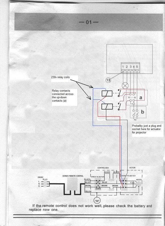
    Here is a diagram which should work. 2 relays with 230v coils, and i have them wired from the screen motor. But they can be taken from anywhere after the control box switching position which switches the up and down wires on and off.
    screenwiring4.jpg


  • Advertisement
  • Closed Accounts Posts: 13,422 ✭✭✭✭Bruthal


    Its a bit tricky to see it but you can see where i have drawn in the 2 relay coils wired from the projector screen onto the diagram you put up, so you need a 3 core cable between the screen and the actuator if you put the relays at the actuator. A box can be made up with the relays in it. A 4 core cable may be needed as most 3 core ones have an earth and its not a good idea to use the earth as the neutral really.

    The actuator will be plugged into its own socket i would imagine, and the relays will operate the actuator contacts as shown in the drawing. there will be no actual electrical connection between the screen and the actuator.

    If the screen is coming down and the actuator is going the wrong way, then you just swap the red wire on one relay with the black on the other in the drawing above. Once the actuator has limit switches like you said, then it should stop once its fully open or closed even of the screen is still moving.

    Sometimes it is a good idea to put the feed of eachrelay through a normaly closed (n/c) of the other relay as a failsafe. But i would say it shoud be ok without that in this setup.


  • Closed Accounts Posts: 13,422 ✭✭✭✭Bruthal


    Just looking in the diagram you put up and noticed the capacitor, not sure where the capacitor at the motor is connected to, or if it might bring on whatever of the relays that should be off when the other one is on. So it might be an idea to connect 2 relays to the screen as shown but without their contacts connected to the actuator, and make sure only one at a time operates, and not both.

    It should not cause that to happen as the unused part of the motor winding will also be connected to the capacitor.


  • Registered Users Posts: 1,026 ✭✭✭Gulliver


    robbie7730 wrote: »
    Here is a diagram which should work. 2 relays with 230v coils, and i have them wired from the screen motor. But they can be taken from anywhere after the control box switching position which switches the up and down wires on and off.
    screenwiring4.jpg

    That's great, thanks for all your help. As I don't have the switching units A and B in that diagram, just the bare actuator can I wire straight from the relay to terminals 3, 4 and 5?


  • Closed Accounts Posts: 13,422 ✭✭✭✭Bruthal


    Gulliver wrote: »
    That's great, thanks for all your help. As I don't have the switching units A and B in that diagram, just the bare actuator can I wire straight from the relay to terminals 3, 4 and 5?

    Yes just get a plug and some flex, the neutral from the plug into terminal 5.

    Now look carefully at the relay contacts. Terminals 3 and 4 are connected to a contact each and this will be the same without the switch sections A and B.

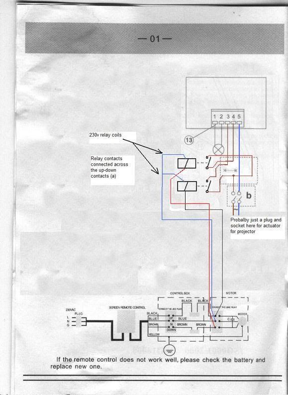
    Now switch B was just a double pole switch, the left side will be live, so the live is going into the other side of both relay contacts which you can see if you follow through the switch B and part A, all that is happening is the live feeds into one contact and loops to the other , so all you do is connect the live from the plug and flex into the other side of both relay contacts that terminals 3 and 4 are into.

    So in effect the neutral is straight to terminal 5.

    Live feeds both relay switch contacts and out the other side of each contact to feed terminals 3 and 4. So when the screen is coming down, the top relay coil is powered on, closing its contact, and feeding live to terminal 4 and so opening the actuator. And the other relay closes it when the screen is going up, and this relay now connects live to terminal 3 and closes the actuator.

    Hopefully that helps anyway.

    A double pole switch on a circuit feeding the actuator can be used instead of the plug and flex setup anyway. Or the plug and flex into a socket with switches.


  • Closed Accounts Posts: 13,422 ✭✭✭✭Bruthal


    Here it is altered slightly. So part B is just a double pole switch feeding the ralay contacts. And out the other side of the contacts to terminals 3 and 4. And neutral to terminal 5. Earth to earth terminal of there is one. screenwiring5.jpg


  • Advertisement
Advertisement