Advertisement
If you have a new account but are having problems posting or verifying your account, please email us on hello@boards.ie for help. Thanks :)
Hello all! Please ensure that you are posting a new thread or question in the appropriate forum. The Feedback forum is overwhelmed with questions that are having to be moved elsewhere. If you need help to verify your account contact hello@boards.ie

Help with LED circuit

Options
  • 19-01-2012 7:20pm
    #1
    Registered Users Posts: 5,391 ✭✭✭


    I know this is probably not the right forum but I can't find anything else which comes close to building cuircuits.

    I'm working on a small project with some LED's, well 36 to be exact :rolleyes:

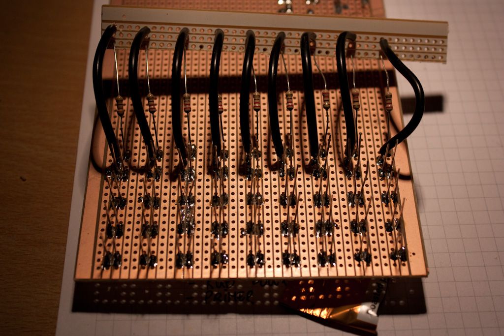
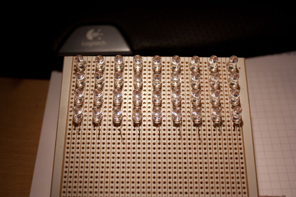
    I have a little test circuit made to see if it all works
    IMG_6743.jpg
    IMG_6744.jpg

    And it works as expected by hooking up + and - to the vero board piece thats sticking out up top with the resistors and black wires in it.

    What I'm trying to figure out is which resistor value am I best of using?
    Using this wizard and the LED spec I get 270 or 180ohm's depending on the forward voltage I use, best go for middle ground and use a 220ohm resistor?

    Another thing I was thinking of was, a way to simplify the circuit a little. Is it possible to omit the resistor on each bank of leds and use one resistor on the vero board? If so what value resistor do I use? (something around 24ohms, 220/9?)


Comments

  • Registered Users Posts: 736 ✭✭✭Timfy


    You could look into a resistor network to tidy up the final design. Each small package can have up to 24 outputs (although 8 - 10 would be more common and I have seen 48) Heat dissipation shouldn't be an issue at these low currents.

    No trees were harmed in the posting of this message, however a large number of electrons were terribly inconvenienced.


  • Registered Users Posts: 5,391 ✭✭✭jozi


    I have absolutely no idea what that is :) Does it change the physical location of the LED's because the way they are is more or less spot on where they need to be + I have lot's of veroboard to work with.

    I forgot to mention my voltage is 12V.

    ---EDIT---

    Is it possible to also place the resistor between the positive and negative rails of LED's? Does it have to be at the end or can it be in the middle?


  • Registered Users Posts: 736 ✭✭✭Timfy


    Hi, It's simply a bunch of resistors in one package - heres some info http://www.digikey.com/Web%20Export/Supplier%20Content/Bourns_118/PDF/Bourns_ResistorNetworks.pdf

    No trees were harmed in the posting of this message, however a large number of electrons were terribly inconvenienced.


  • Registered Users Posts: 5,391 ✭✭✭jozi


    I think I'll stick with what I have. Looks to me the rails are 2 far apart for one to work on the circuit.

    If I can use one resistor on the rail supplying the voltage to all led groups I'd be happy enough.


  • Moderators, Computer Games Moderators Posts: 4,281 Mod ✭✭✭✭deconduo


    jozi wrote: »
    I think I'll stick with what I have. Looks to me the rails are 2 far apart for one to work on the circuit.

    If I can use one resistor on the rail supplying the voltage to all led groups I'd be happy enough.

    The way you have it set up seems like the best. I'd go with one 200ohm resistor per group of 4, which gives them a driving voltage of 2V @ ~20mA. It would be nice to see the full VI curve for the LEDs as that would let us work out the precise driving voltage for 20mA.

    FYI you can't actually put 36 LEDs on a single resistor. If you take the voltage drop across each one as 2V, the most you could put on would be 5.


  • Advertisement
  • Registered Users Posts: 5,391 ✭✭✭jozi


    Thanks Deconduo, I'll go ahead and order a batch of resistors.

    To make it a little more compact can I move the resistor to anywhere on the negative (I think) rail and have power soldered on anywhere as well?

    I may be back with more question as I think I might have one or two set's of LED's that require more groups than what I have done now.


  • Moderators, Computer Games Moderators Posts: 4,281 Mod ✭✭✭✭deconduo


    jozi wrote: »
    Thanks Deconduo, I'll go ahead and order a batch of resistors.

    To make it a little more compact can I move the resistor to anywhere on the negative (I think) rail and have power soldered on anywhere as well?

    I may be back with more question as I think I might have one or two set's of LED's that require more groups than what I have done now.

    Basically you want something like this: (Ignore the R values)

    9s6qs.png

    You can expand that from 9 rows to as many as you want, as long as your power source can handle it.


  • Registered Users Posts: 5,391 ✭✭✭jozi


    Nice one and that looks like it alright. Power will come from a car battery.

    Any good source for resistors or google + ebay and which ever is cheapest?


    ---edit---

    This work: http://www.ebay.co.uk/itm/1-4-WATT-METAL-FILM-RESISTOR-200-OHM-Pack-200-/230681104057?pt=UK_BOI_Electrical_Components_Supplies_ET&hash=item35b5aa4eb9


  • Moderators, Computer Games Moderators Posts: 4,281 Mod ✭✭✭✭deconduo


    jozi wrote: »
    Nice one and that looks like it alright. Power will come from a car battery.

    Any good source for resistors or google + ebay and which ever is cheapest?


    ---edit---

    This work: http://www.ebay.co.uk/itm/1-4-WATT-METAL-FILM-RESISTOR-200-OHM-Pack-200-/230681104057?pt=UK_BOI_Electrical_Components_Supplies_ET&hash=item35b5aa4eb9

    I get all my stuff from here:
    http://radionics.rs-online.com/web/home.html

    Delivery is quick and the prices are good. These would do the job:
    http://radionics.rs-online.com/web/p/products/7077619/


Advertisement