Advertisement
If you have a new account but are having problems posting or verifying your account, please email us on hello@boards.ie for help. Thanks :)
Hello all! Please ensure that you are posting a new thread or question in the appropriate forum. The Feedback forum is overwhelmed with questions that are having to be moved elsewhere. If you need help to verify your account contact hello@boards.ie

Transformer question

Options
  • 12-03-2012 9:33am
    #1
    Registered Users Posts: 117 ✭✭


    Hello,

    I have a technical theroetical question please if anyone can advise,

    I have a transformer plug that takes in 230v AC or DC & transforms it into 12v DC, when you divide the 12v into the 230v that gives you a ratio of 19.16 times the power is stepped down.

    Now the question,

    If i used the same transformer with a 65v DC supply, given that the ratio is 19.16 times stepped down from 230v to 12v, will the same step down ratio apply giving me an output of 3.39v DC at the other end if it is only 65v going in?


Comments

  • Registered Users Posts: 2,637 ✭✭✭brightspark


    It won't work, transformers only work on AC.


  • Registered Users Posts: 117 ✭✭Uncorruptable


    It won't work, transformers only work on AC.

    Thanks for this, i am not doubting you are right at all, so i must be mistaken some how, as the Transformer i have i could have sworn says on it AC or DC.

    I must have read it wrong.

    Anyway, i need to be able to switch the DC to AC, yes?


  • Registered Users Posts: 936 ✭✭✭bassey


    It probably transforms 230 V AC down to 12 V AC then converts it to 12 V DC


  • Moderators, Home & Garden Moderators, Technology & Internet Moderators, Regional East Moderators Posts: 12,592 Mod ✭✭✭✭2011


    Thanks for this, i am not doubting you are right at all, so i must be mistaken some how, as the Transformer i have i could have sworn says on it AC or DC.

    I must have read it wrong.

    Anyway, i need to be able to switch the DC to AC, yes?

    You may well be looking at a Switched Mode Power Supply, (SMPS). These units are commonly used instead of a small transformer/rectifier for may electronic appliances.

    As the other posters have said transformers work on AC, not DC.


  • Registered Users Posts: 117 ✭✭Uncorruptable


    One more question which may help in waht i am attempting,

    Is the term 'Constant Current' used in America the same as 'Direct Current' used in Europe?


  • Advertisement
  • Registered Users Posts: 589 ✭✭✭danjo


    No. they are different. DC is DC and constant current is constant current across the globe.
    A DC source may or may not provide constant current.

    DC describes direct current as opposed to AC, alternating current.


  • Registered Users Posts: 117 ✭✭Uncorruptable


    OK, heres the story that i need a little pointer on,

    I have a Digital projector, bulb has expired on it & they are up to & over €300 to replace with a lamp life of only 2000 hours.

    After some research i found this little gem,

    http://www.luminus.com/products/datasheets/Luminus_CST-90-W_Datasheet.pdf

    Now, i have stripped out the lamp housing of the original bulb & have this now fixed in position at the right distance to project light onto the prisms inside the lamp house.

    As per the posts above my problem has arisen as it states in the datasheet a 'Forward voltage' of 3.7v to get max lumens.

    i thought this was a little low for such high output & queried it with the manafacturer, this was their reply,

    Applying a voltage to the LED is not recommended. The CST-90 (and all Luminus LEDs) requires a constant current supply. Typical drive currents are 3.15 A, 9 A and 13.5 A. The choice of drive current depends your lumen requirements—you get up to 1000 lumens at 3.15 A. The supply must be constant current, with a compliance voltage at least as high as the Vf max listed in the datasheet (3.9 V at 3.15 A).
    Let me know if you have questions.
    Can you tell us a little about your application?

    I am confused on this as it says at the start,

    'Applying a voltage to the LED is not recommended',

    but then goes on to say,

    'The supply must be constant current, with a compliance voltage at least as high as the Vf max listed in the datasheet (3.9 V at 3.15 A).

    I want to use a transformer that gives out 3.7v DC thhat plugs into your normal house socket, i communicated this to the manafacturers who replied,

    Refer to http://www.maxim-ic.com/app-notes/index.mvp/id/3256 and the attached app note.
    The drive current has to be DC but the controller should output current, not voltage, as is the case with the transformer.

    I am still not 100% clear whether or not i can use the transformer, it looks llike i can but i dont want to bloow the LED.

    Can someone with superior electrical knowledge please advise whether or not i can use the transformer please, i am thinking the only adverse affect possible if i do is the light being emitted may dull & brighten if there is any variance in the current.

    Please advise.


  • Moderators, Home & Garden Moderators, Technology & Internet Moderators, Regional East Moderators Posts: 12,592 Mod ✭✭✭✭2011


    OK, heres the story that i need a little pointer on,

    I have a Digital projector, bulb has expired on it & they are up to & over €300 to replace with a lamp life of only 2000 hours.

    After some research i found this little gem,

    http://www.luminus.com/products/datasheets/Luminus_CST-90-W_Datasheet.pdf

    Now, i have stripped out the lamp housing of the original bulb & have this now fixed in position at the right distance to project light onto the prisms inside the lamp house.

    The first thing that I would be thinking is that although your alternative may work I doubt that it will work very well. The €300 lamp that is designed specifically for the projector will have very particular properties that your LED lamp will not be able to meet. I would think that the most important one will be the Color Rendering Index, (CRI).

    Read about this here:

    http://en.wikipedia.org/wiki/Color_rendering_index

    This will have a dramatic impact on your picture quality and colors.


  • Moderators, Home & Garden Moderators, Technology & Internet Moderators, Regional East Moderators Posts: 12,592 Mod ✭✭✭✭2011


    I had a read of the datasheets, interesting stuff!
    I think I understand and will try to reply later.


  • Registered Users Posts: 2,637 ✭✭✭brightspark


    LED's being semiconductors do not have linear responses to voltage variations etc, a small increase in voltage may cause a large destructive current to flow.

    If you look at page 9 of the data sheet there is a chart labelled 'Forward Current vs. Forward Voltage'

    Note how the current rapidly increases between 3.5V and 4V!

    Also the chart above it shows that the brightnes will be 3 1/2 times brighter at 3.9V (13.5A) than at 3.3V (3A)

    A constant current power supply will automatically vary the voltage to maintain the required current flow.

    If you google 'constant current LED drivers' you may find one that suits your needs.


  • Advertisement
  • Moderators, Home & Garden Moderators, Technology & Internet Moderators, Regional East Moderators Posts: 12,592 Mod ✭✭✭✭2011


    As per the posts above my problem has arisen as it states in the datasheet a 'Forward voltage' of 3.7v to get max lumens.

    This just tells you that it is polarity conscious and that maximum light output will occur when it is drawing 3.7VDC.
    i thought this was a little low for such high output & queried it with the manafacturer, this was their reply,
    The higher the light output is proportional to the current drawn, not the voltage.
    Applying a voltage to the LED is not recommended.

    I would think that this should read:
    Applying a voltage source to the LED is not recommended.

    Applying a current source to the LED is required.
    The CST-90 (and all Luminus LEDs) requires a constant current supply. Typical drive currents are 3.15 A, 9 A and 13.5 A.

    A current source varies the output voltage to maintain a particular current. A voltage source will output a constant voltage output regardless of the current draw (up to a point).
    The supply must be constant current, with a compliance voltage at least as high as the Vf max listed in the datasheet (3.9 V at 3.15 A).

    So this means that a DC current source must be used to supply the LED within the voltage specifications as outlined on the data sheet.
    I want to use a transformer that gives out 3.7v DC thhat plugs into your normal house socket, i communicated this to the manafacturers who replied,

    Refer to http://www.maxim-ic.com/app-notes/index.mvp/id/3256 and the attached app note.
    The drive current has to be DC but the controller should output current, not voltage, as is the case with the transformer.

    Basically they said that the transformer / rectifier arrangement (or SMPS) that you have is not suitable as it is a voltage source, not a current source.
    I am still not 100% clear whether or not i can use the transformer, it looks llike i can but i dont want to bloow the LED.
    I would think not.

    At work I use analog signals to and from control systems to control different processes, speeds of motors, temperatures, pressures, flow etc..

    This is often achieved by varying the of current signals from 4 to 20mA. The voltage is not relevant once it is within tolerance.

    I hope this helps.


  • Closed Accounts Posts: 13,422 ✭✭✭✭Bruthal


    OK, heres the story that i need a little pointer on,

    I have a Digital projector, bulb has expired on it & they are up to & over €300 to replace with a lamp life of only 2000 hours.

    After some research i found this little gem,

    http://www.luminus.com/products/datasheets/Luminus_CST-90-W_Datasheet.pdf

    Now, i have stripped out the lamp housing of the original bulb & have this now fixed in position at the right distance to project light onto the prisms inside the lamp house.

    As per the posts above my problem has arisen as it states in the datasheet a 'Forward voltage' of 3.7v to get max lumens.

    i thought this was a little low for such high output & queried it with the manafacturer, this was their reply,

    Applying a voltage to the LED is not recommended. The CST-90 (and all Luminus LEDs) requires a constant current supply. Typical drive currents are 3.15 A, 9 A and 13.5 A. The choice of drive current depends your lumen requirements—you get up to 1000 lumens at 3.15 A. The supply must be constant current, with a compliance voltage at least as high as the Vf max listed in the datasheet (3.9 V at 3.15 A).
    Let me know if you have questions.
    Can you tell us a little about your application?

    I am confused on this as it says at the start,

    'Applying a voltage to the LED is not recommended',

    but then goes on to say,

    'The supply must be constant current, with a compliance voltage at least as high as the Vf max listed in the datasheet (3.9 V at 3.15 A).

    I want to use a transformer that gives out 3.7v DC thhat plugs into your normal house socket, i communicated this to the manafacturers who replied,

    Refer to http://www.maxim-ic.com/app-notes/index.mvp/id/3256 and the attached app note.
    The drive current has to be DC but the controller should output current, not voltage, as is the case with the transformer.

    I am still not 100% clear whether or not i can use the transformer, it looks llike i can but i dont want to bloow the LED.

    Can someone with superior electrical knowledge please advise whether or not i can use the transformer please, i am thinking the only adverse affect possible if i do is the light being emitted may dull & brighten if there is any variance in the current.

    Please advise.

    What they mean about applying a voltage is not recommended,,,,is not to just apply any voltage to the LED, as most voltage will be above its rating, although many small wall adaptors would not be able to supply enough curent to damage it anyway.

    If i was doing it myself i would make up a microcontroller controlling a mosfet for a pwm output setup to get it to work at the desired current, and supply it from 12v, or maybe even a laptop power supply which is 19v and has the rating required.

    But there would be various ways to drive this led. A 3.3v regulator rated to the LED current would be one way, and supplied from an adequate power supply. A switching regulator powering it could be run from a 1 amp 12v dc transformer for the 3.3v setup.

    Or a simple driver circuit can be made from a mosfet transistor and a couple of other components.

    Led drivers can also be bought.


  • Registered Users Posts: 117 ✭✭Uncorruptable


    2011 wrote: »
    The first thing that I would be thinking is that although your alternative may work I doubt that it will work very well. The €300 lamp that is designed specifically for the projector will have very particular properties that your LED lamp will not be able to meet. I would think that the most important one will be the Color Rendering Index, (CRI).

    Read about this here:

    http://en.wikipedia.org/wiki/Color_rendering_index

    This will have a dramatic impact on your picture quality and colors.

    I hear you, the colour temp of the chip i bought is 4500k, i intended also to adjust the actual output from the laptop feeding the image to try & compensate as much as possible, this is all expperimental to see if an acceptable image can be acheived.
    LED's being semiconductors do not have linear responses to voltage variations etc, a small increase in voltage may cause a large destructive current to flow.

    If you look at page 9 of the data sheet there is a chart labelled 'Forward Current vs. Forward Voltage'

    Note how the current rapidly increases between 3.5V and 4V!

    Also the chart above it shows that the brightnes will be 3 1/2 times brighter at 3.9V (13.5A) than at 3.3V (3A)

    A constant current power supply will automatically vary the voltage to maintain the required current flow.

    If you google 'constant current LED drivers' you may find one that suits your needs.

    Thanks for this, i will check it out later.
    robbie7730 wrote: »
    What they mean about applying a voltage is not recommended,,,,is not to just apply any voltage to the LED, as most voltage will be above its rating, although many small wall adaptors would not be able to supply enough curent to damage it anyway.

    If i was doing it myself i would make up a microcontroller controlling a mosfet for a pwm output setup to get it to work at the desired current, and supply it from 12v, or maybe even a laptop power supply which is 19v and has the rating required.

    But there would be various ways to drive this led. A 3.3v regulator rated to the LED current would be one way, and supplied from an adequate power supply. A switching regulator powering it could be run from a 1 amp 12v dc transformer for the 3.3v setup.

    Or a simple driver circuit can be made from a mosfet transistor and a couple of other components.

    Led drivers can also be bought.

    Would this PSU be any use? (Note 3.3v @ 10.0a)

    197668.jpg


  • Closed Accounts Posts: 13,422 ✭✭✭✭Bruthal


    Would this PSU be any use? (Note 3.3v @ 10.0a)

    197668.jpg

    That looks like it would drive it directly. Dont forget a heat sink will be needed behind the LED board, probably with heat conducting paste between them.


  • Registered Users Posts: 117 ✭✭Uncorruptable


    robbie7730 wrote: »
    That looks like it would drive it directly. Dont forget a heat sink will be needed behind the LED board, probably with heat conducting paste between them.

    Cheers, i'll have to look at a suitable heat sink now so.


  • Moderators, Home & Garden Moderators, Technology & Internet Moderators, Regional East Moderators Posts: 12,592 Mod ✭✭✭✭2011


  • Moderators, Home & Garden Moderators, Technology & Internet Moderators, Regional East Moderators Posts: 12,592 Mod ✭✭✭✭2011


    robbie7730 wrote: »
    If i was doing it myself i would make up a microcontroller controlling a mosfet for a pwm output setup to get it to work at the desired current, and supply it from 12v, or maybe even a laptop power supply which is 19v and has the rating required.

    So you would:
    1) Measure the output current
    2) Calculate the error (difference between the actual current and the set point)
    3) Using PWM (via a microrprocessor and a MOSFET) adjust the duty cycle to ensure that the correct current is maintained.

    Is that correct?


  • Closed Accounts Posts: 13,422 ✭✭✭✭Bruthal


    2011 wrote: »
    So you would:
    1) Measure the output current
    2) Calculate the error (difference between the actual current and the set point)
    3) Using PWM (via a microrprocessor and a MOSFET) adjust the duty cycle to ensure that the correct current is maintained.

    Is that correct?

    Similar to that.

    If we want 3.15 amps through the led from a 12v supply, connect the led through the mosfet, and a 1 ohm resistor in series, a 10 watt one. And set the pwm on the micro controller to give a 3.15A current through the led, just by starting off well below the required level, and increment up by changing the on v off time in the program, until the desired current is obtained.

    The micro controller circuit would need a 5v regulator to power it. Common the negatives of this and the n channel logic level (5v gate full on) mosfet , and the 12v dc, (or 24v etc) can be switched via the pwm output.

    Two 1 ohm resistors in parallel would give a 0.5ohm 20 watt resistor, but the on duty cycle would need to be shortened then.

    A 5 amp fuse can be put directly into the lead to the led as well.

    3.15 amps is as high as it can go with a 1 ohm 10 watt resistor. But a 0.5 ohm resistor of 10 watts would give over 4 amps allowance. So two 1 ohm ones in parallel would cover over 6 amps through the led.

    A lower voltage supply and the duty cycle on time would be increased and vice versa. If the 3.3v supply was used, it would be powered directly.

    That would be one possible way. I used similar as a dimming method for dimming battery powered leds.

    The ideal power supply for the above is a laptop power supply.

    The 3,3v power supply he linked should power it directly though. The good thing with the micro controller setup is it can be adjusted.

    It would be more experimental on my part, as i have not had to do the particular task the OP is doing. But i have used it for dimming led`s as said. And am presently making a radio control car for someone, and I am using a micro controller to convert the radio pwm`s into forward and reverse commands for motors to directly drive the tracks on it so push buttons can drive it instead of sticks, with a pwm count up for soft starting when a button is pressed.


  • Registered Users Posts: 5,379 ✭✭✭DublinDilbert


    If your not using an inductor to give you an energy conversion stage, you'll have very high losses in the system and can put very large transients onto the LED.

    Microchip do a good app note on using a micro to do this:-
    http://ww1.microchip.com/downloads/en/appnotes/00874C.pdf

    You could in theory just use a comparitor like is shown in firgure 3 of the app note, but the switching frequency would then be a function of the inductor size + power supply level etc...

    The simplest method of doing it would probably be a PWM Driver IC (UC3844) to control the mosfet. Then feed back the voltage across the sense resistor as the voltage you are trying to control. The UC3844 does have a current sens input, but this can just be used for enabling / dissabling the device.

    With the UC3844 its target voltage is 2.5V from memory, so if you want 3.15A out, your current sense resistor is 2.5/3.15= 0.8R. This resistor will dissipate almost 8Watts. So you may want to choose a slightly different PWM Driver IC.


  • Moderators, Home & Garden Moderators, Technology & Internet Moderators, Regional East Moderators Posts: 12,592 Mod ✭✭✭✭2011


    Interesting post Dilbert.

    However, as I said earlier I think that if the OP gets this working he will be disappointed with the picture quality. There is a reason that projector lamps cost "up to & over €300 to replace with a lamp life of only 2000 hours"

    They are very specialized.


  • Advertisement
  • Closed Accounts Posts: 13,422 ✭✭✭✭Bruthal


    2011 wrote: »
    Interesting post Dilbert.

    However, as I said earlier I think that if the OP gets this working he will be disappointed with the picture quality. There is a reason that projector lamps cost "up to & over €300 to replace with a lamp life of only 2000 hours"

    They are very specialized.

    They are probably a bit more expensive than their specialized criteria suggest though. And they are specialized mainly due to the high operating temperature and output level, quartz glass etc. Some of these criteria would not be required if LED lighting replaces them.

    Im not saying the OP`s led will work fine either. But some of the expense reasons for lamps wont be a problem for LEDs if they do start to replace lamps in projectors at some stage in general.

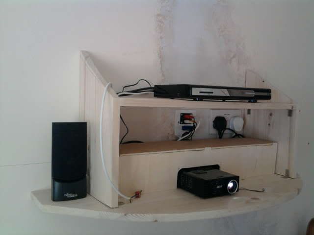
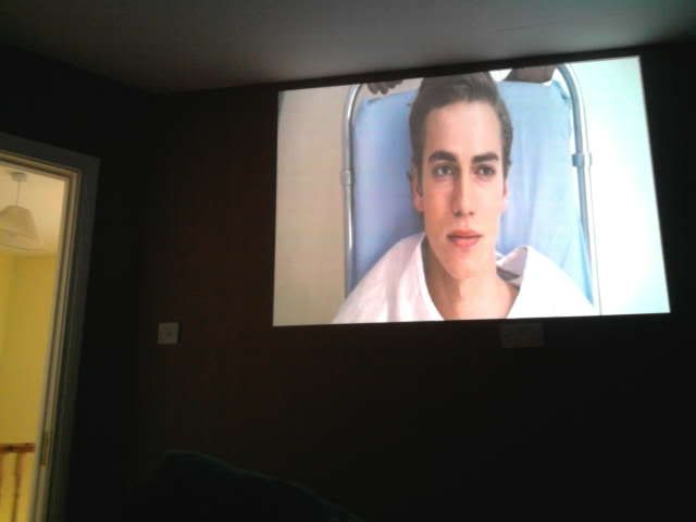
    Im uing a small projector here with a LED in it coincidently. Great for passing the time while laid up, even though ironically it contributed to being laid up:D. Its on day and night.

    Still have to paint the chased and replastered wall. And tidy and paint the shelf. This shelf was the cause of the stairs slip.
    Photo0456.jpg

    Photo0403.jpg


  • Registered Users Posts: 117 ✭✭Uncorruptable


    197668.jpg

    Just noticed, i dont think this PPSU wil do, it outputs 300w, the chips have a max input of 50w,

    http://www.luminus.com/products/CST-90.html

    Would the 300w be overall for all the supplies coming from this PSU?
    How would i determine the 3.3v @ 10amp watt output?

    Sorry for all the questions, my next project will be to take a few courses in electronics:D


  • Closed Accounts Posts: 13,422 ✭✭✭✭Bruthal


    Just noticed, i dont think this PPSU wil do, it outputs 300w, the chips have a max input of 50w,

    http://www.luminus.com/products/CST-90.html

    Would the 300w be overall for all the supplies coming from this PSU?
    How would i determine the 3.3v @ 10amp watt output?

    Sorry for all the questions, my next project will be to take a few courses in electronics:D

    The 300w will just be the total output the power supply can deliver. If you connect something to it that takes 50 watts, the power supply will just supply 50 watts.

    So if this led takes 3.15 amps from the 3.3v supply, that will be 10 watts.


  • Registered Users Posts: 117 ✭✭Uncorruptable


    robbie7730 wrote: »
    The 300w will just be the total output the power supply can deliver. If you connect something to it that takes 50 watts, the power supply will just supply 50 watts.

    So if this led takes 3.15 amps from the 3.3v supply, that will be 10 watts.

    Thanks for all your help, i will give it lash now that i have almost settled all my hesitations around this, i will report back with images of results once i fire this up.

    Cheers again.


  • Closed Accounts Posts: 13,422 ✭✭✭✭Bruthal


    Thanks for all your help, i will give it lash now that i have almost settled all my hesitations around this, i will report back with images of results once i fire this up.

    Cheers again.

    Do you have a heat sink? make sure you connect the LED to the 3,3v part of that supply. Do you have a voltmeter?

    I would agree with 2011s view that getting a decent image will possibly be difficult. The proper bulbs have high quality reflectors etc.

    But worth experimenting with anyway.


  • Registered Users Posts: 117 ✭✭Uncorruptable


    robbie7730 wrote: »
    Do you have a heat sink? make sure you connect the LED to the 3,3v part of that supply. Do you have a voltmeter?

    I would agree with 2011s view that getting a decent image will possibly be difficult. The proper bulbs have high quality reflectors etc.

    But worth experimenting with anyway.

    Fortunatley the PSU gives the orange wiring as the 3.3v, however, i will have my sparks test the wires for me to ensure i have correct ones & + & -

    I have a few heat sinks from PC's that were used on processers etc, i will choose suitable one for size of enclosure & position it with grills horizontally which will then be in direct lline of the internal fans of the PJ.

    Where & what is best to paste/cement the chip to the sink?


  • Moderators, Home & Garden Moderators, Technology & Internet Moderators, Regional East Moderators Posts: 12,592 Mod ✭✭✭✭2011


    Fortunatley the PSU gives the orange wiring as the 3.3v, however, i will have my sparks test the wires for me to ensure i have correct ones & + & -

    Yes, that is important. The datasheet shows this device to be polarity consious.

    Let us know how it turns out. I would be interested.


  • Moderators, Home & Garden Moderators, Technology & Internet Moderators, Regional East Moderators Posts: 12,592 Mod ✭✭✭✭2011


    robbie7730 wrote: »
    Im uing a small projector here with a LED in it coincidently. Great for passing the time while laid up, even though ironically it contributed to being laid up:D. Its on day and night.

    Interesting.
    It came with the LED lamp??

    Still laid up? That is dragging on a while now.
    Get well soon!


  • Registered Users Posts: 117 ✭✭Uncorruptable


    robbie7730 wrote: »
    I would agree with 2011s view that getting a decent image will possibly be difficult. The proper bulbs have high quality reflectors etc.

    But worth experimenting with anyway.

    I am intersted myself to see what light i acheive from it.

    The idea behind it is that with all normal bulbs you used reflectors to channel the light towards the prisms & allso to capture all of the light being emitted as the bulbs were placed hhorizontal in the light tunnel.

    With the chip, the Diodes emit the light directly off the board which is then dispersed by the convex dome lens located above them.

    The light will be magnified by the lens & dispersed at a 90' angle which placed just correctly will allow all of the emitted light to hit the prisms.

    In theory you should not really have any lumen loss, you will have colour issues as the reflectors in the PJ bulbs are Dichroic but i will attempt to compensate for that with the laptop to the best i can.

    The real cahllenge i think will be finding dead centre for the LED, i anticipate i will get it fairly accurate but potentially could see some blurring if its off to much.


  • Advertisement
  • Closed Accounts Posts: 13,422 ✭✭✭✭Bruthal


    2011 wrote: »
    Interesting.
    It came with the LED lamp??

    Yes its just a small LED one, not as powerful as a bulb one, but very good just the same.
    Still laid up? That is dragging on a while now.
    Yes it sure is, but finally the x ray on monday just gone shows the healing is underway. It was slow to start. Its a right pain in the back side at this stage.
    Get well soon!
    Thanks.


Advertisement