Advertisement
If you have a new account but are having problems posting or verifying your account, please email us on hello@boards.ie for help. Thanks :)
Hello all! Please ensure that you are posting a new thread or question in the appropriate forum. The Feedback forum is overwhelmed with questions that are having to be moved elsewhere. If you need help to verify your account contact hello@boards.ie

Automatic chicken door

Options
  • 05-08-2012 1:15pm
    #1
    Closed Accounts Posts: 1,250 ✭✭✭


    Hi guys , hope this is the right forum .
    I've automated my chicken coop door using a spring to pull the door open and an old drill motor attached to string to pull it closed . I have limit switches and it's closing fine but opening way to quickly .
    Is there a resistor or some sort that can be attached to slow the motor when opening ? It's powered off a 12 v battery or sometimes a 12 v trafo .


Comments

  • Closed Accounts Posts: 4,431 ✭✭✭M cebee


    robbie will prob know if he's about:D


  • Registered Users Posts: 4,745 ✭✭✭meercat


    love to see this
    any chance of a video?


  • Closed Accounts Posts: 1,250 ✭✭✭Thunderbird2


    If I new how to get one up I would !!
    It's handy as its on a timer to keep the rooster in till ten !


  • Registered Users Posts: 1,605 ✭✭✭crasy dash


    You thought of everything there haha I like it


  • Closed Accounts Posts: 1,250 ✭✭✭Thunderbird2


    Well I didn't want to pay €100 + for one :/
    The motors on its own power supply . The relay is powered by a transformer plugged into a timer ( I have to swap this with a dusk till dawn timer that closes it at dusk and opens it 9 hours later ) . Timer turns on and the relay switches over and the door closes.


  • Advertisement
  • Registered Users Posts: 4,745 ✭✭✭meercat


    If I new how to get one up I would !!
    It's handy as its on a timer to keep the rooster in till ten !

    pics then

    go on ,we need to see it
    :D


  • Closed Accounts Posts: 1,250 ✭✭✭Thunderbird2


    If I put a vid on YouTube will a link work ?
    How do I post pics??? :confused:


  • Registered Users Posts: 5,379 ✭✭✭DublinDilbert


    Can you get a 6v trafo to run the motor? Or maybe 8v?

    A resistor will also work, but it will need to be a power resistor which can handle enough power.


  • Closed Accounts Posts: 1,250 ✭✭✭Thunderbird2


    12v is needed to close the door due to the spring .


  • Registered Users Posts: 4,745 ✭✭✭meercat


    If I put a vid on YouTube will a link work ?
    How do I post pics??? :confused:

    yeah link will work


  • Advertisement
  • Registered Users Posts: 5,379 ✭✭✭DublinDilbert


    Ahhh ok so you just need to slow it in one direction only.

    I would guess you need to look at your spring again. The spring should be there to counter balance the weight of the door / flap. Then the motor has roughly the same effort in each direction.


  • Closed Accounts Posts: 13,422 ✭✭✭✭Bruthal


    Well I didn't want to pay €100 + for one :/
    The motors on its own power supply . The relay is powered by a transformer plugged into a timer ( I have to swap this with a dusk till dawn timer that closes it at dusk and opens it 9 hours later ) . Timer turns on and the relay switches over and the door closes.

    So when the drill motor pulls it closed, a limit switch opens to stop drill motor when the door is closed all the way?

    How does it then open it? Reverse the drill motor to release string, and spring pulls open?

    As others said, running it with 6v or another suitable voltage will slow it.

    Or making the drill motor pulley with the string on it smaller, and/or move the attach point to the door further from the hinge.


  • Moderators, Home & Garden Moderators, Technology & Internet Moderators, Regional East Moderators Posts: 12,593 Mod ✭✭✭✭2011


    Or you could leave it as it as it is as make chicken McNuggets :D:D


  • Registered Users Posts: 2,234 ✭✭✭deandean


    Ha i made one of those about 20 years ago. I used an old Venner or Veeder Root electromechanical timer that adjusted itself for daylight hours, (used to be used for street lights).

    But I used a geared motor, it took about 30s for the door to open/close.


  • Registered Users Posts: 270 ✭✭liveandnetural


  • Closed Accounts Posts: 1,250 ✭✭✭Thunderbird2


    Those prices are the reason I made my own . They don't lock the door either which is a let down because of the prices .
    When mine is closed its locked up fairly tight


  • Registered Users Posts: 1,935 ✭✭✭whizbang


    you need a resistor in series in the circuit for open, put a diode parallel with resistor in the forward direction to close.
    You'll need a serious diode, salvage the big one from an old computer power supply. maybe try 4-8ohm 10Watt resistor. better still, get a bunch of 1ohm 2W, and add or subtract as needed.


  • Closed Accounts Posts: 1,250 ✭✭✭Thunderbird2


    I got it sorted :) I made an articulated type arm and attached it to the drill motor .
    Door opens fast but doesn't have enough force to cause damage .
    Now the door isn't affected by winds :-)
    Vid coming soon


  • Closed Accounts Posts: 1,250 ✭✭✭Thunderbird2


  • Registered Users Posts: 4,745 ✭✭✭meercat


    just edited your link here(yours didnt work)
    thanks for posting


  • Advertisement
  • Closed Accounts Posts: 1,250 ✭✭✭Thunderbird2


    Oh :/ il post another


  • Closed Accounts Posts: 13,422 ✭✭✭✭Bruthal


    Oh :/ il post another

    Here you go.


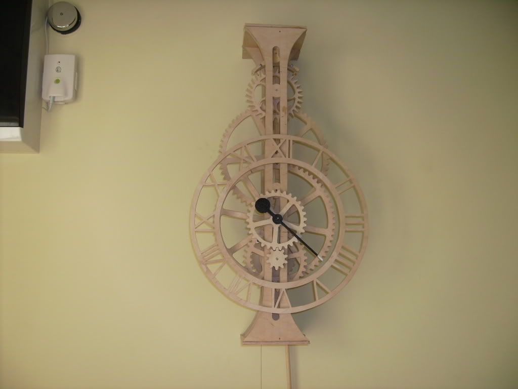
    And here is a timer for it :)
    PICT0280.jpg


  • Closed Accounts Posts: 1,250 ✭✭✭Thunderbird2


    Haha it works on a timer . The timer turns on a trafo for the DPDT relay .the motor has its own power supply


  • Closed Accounts Posts: 13,422 ✭✭✭✭Bruthal


    Haha it works on a timer .
    I know, thats my home made plywood timer

    The timer turns on a trafo for the DPDT relay .the motor has its own power supply

    A DPDT relay for polarity reversing perhaps.


  • Closed Accounts Posts: 13,422 ✭✭✭✭Bruthal


    An interesting one would have been to use a microcontroller chip to output a pwm that counts up and then down for the on to off ratio, each time the relay changes over, so giving a soft start and also a soft stop. Any speed could be programmed in for the door movement.

    Output it through a power transistor then, to drive the battery drill motor.


  • Closed Accounts Posts: 1,250 ✭✭✭Thunderbird2


    robbie7730 wrote: »
    An interesting one would have been to use a microcontroller chip to output a pwm that counts up and then down for the on to off ratio, each time the relay changes over, so giving a soft start and also a soft stop. Any speed could be programmed in for the door movement.

    Output it through a power transistor then, to drive the battery drill motor.


    Do you have any links or diagrams for this method ??
    I'm making another one using a door that slides up and down for a family member .


  • Closed Accounts Posts: 13,422 ✭✭✭✭Bruthal


    Do you have any links or diagrams for this method ??
    I'm making another one using a door that slides up and down for a family member .

    Well i have made the circuits myself in a couple of items, and then have to write up a program to run on the chip. I did this for soft starting of dc motors, and am going to do one for the car fan heater motor for selectable speeds, which has blown its resistor pack and will only work on full speed at present:D

    But a 555 timer chip can also be used to make a pwm circuit, with a control pot to set the speed. It wont have a soft start but a variable speed setting that you can manually set will do perfect for your applications. The chip then has its output switching a transistor in the pwm pattern, which can then switch the motor.

    Look up 555 pwm circuits.
    Here is one anyway

    You can see the irf540 mosfet which is a power transistor. It will switch the negative leg of the load being switched, as seen in the diagram.

    I used a very similar circuit for manual control of radio control servos in a project a couple of years ago. But have since went the microcontroller route. But that 555 chip setup might do the job.

    EDIT. IRF520 in that diagram, I used IRF540N ones in a few applications. It depends on the motor load.


Advertisement