Advertisement
If you have a new account but are having problems posting or verifying your account, please email us on hello@boards.ie for help. Thanks :)
Hello all! Please ensure that you are posting a new thread or question in the appropriate forum. The Feedback forum is overwhelmed with questions that are having to be moved elsewhere. If you need help to verify your account contact hello@boards.ie

motor control interlocks

Options
  • 26-07-2013 6:08pm
    #1
    Registered Users Posts: 3


    Hi
    I am new to this forum craic so I'm just going to ask, perhaps I should research and not be so lazy but hear goes.

    I have 1 direct on line motor and 1 star-delta motor what I need is a control circuit to interlock the direct on line motor to start first and stop last with a time delay between the small motor and big one on start and a delay between the big motor and small one on stop. A diagram is all I need


Comments

  • Registered Users Posts: 2,637 ✭✭✭brightspark


    Out of curiosity what are the motors driving?

    Is this an actual installation or just a project?

    I think you will need at least 2 separate timers, in addition to the star delta timer.

    It might be simpler to use one of the small brick PLCs available, and probably would be as cheap as a couple of timers anyway.

    http://radionics.rs-online.com/web/p/logic-modules/0499756/

    You may also need to consider an emergency stop circuit to stop the small motor quickly in the event of an emergency instead of waiting for the large motor to stop first! But that will of course depend on the application.


  • Registered Users Posts: 3 MP Maint


    Thanks for the response Brightspark,

    I have 2 mf timers and all the gear im struggling with the sequence, if I had a diagram it would be sorted.


  • Moderators, Home & Garden Moderators, Technology & Internet Moderators, Regional East Moderators Posts: 12,593 Mod ✭✭✭✭2011


    MP Maint wrote: »
    Thanks for the response Brightspark,

    I have 2 mf timers and all the gear im struggling with the sequence, if I had a diagram it would be sorted.

    I agree with Brightspark on this. What you are asking for is possible, but complicated using relay logic alone. It would be normal to do this sort of motor control with a PLC.

    I don't want to be pedantic, but interlocks are related to safety and what you have asked for appears to be related to control.

    Have you connection details and data sheet for the timers??


  • Registered Users Posts: 3,544 ✭✭✭LeBash


    Can you not just get your hand on a diagram from a star delta?


  • Closed Accounts Posts: 13,422 ✭✭✭✭Bruthal


    LeBash wrote: »
    Can you not just get your hand on a diagram from a star delta?

    There is a little more to it than a simple star delta circuit.


  • Advertisement
  • Closed Accounts Posts: 13,422 ✭✭✭✭Bruthal


    2011 wrote: »
    I don't want to be pedantic, but interlocks are related to safety and what you have asked for appears to be related to control.
    Interlocking (electrical) can be purely for control purposes though, to ensure one motor has to be running before the other.
    Have you connection details and data sheet for the timers??

    Possibly them MCB size multi function timers.

    Whats the application, an idler motor convertor powering a 3 phase motor or something?


  • Moderators, Home & Garden Moderators, Technology & Internet Moderators, Regional East Moderators Posts: 12,593 Mod ✭✭✭✭2011


    Bruthal wrote: »
    Interlocking (electrical) can be purely for control purposes though, to ensure one motor has to be running before the other.

    I don't agree, unless there is a safety aspect to it.

    a device, esp one operated electromechanically, used in a logic circuit or electrical safety system to prevent an activity being initiated unless preceded by certain events


    http://www.collinsdictionary.com/dictionary/english/interlock


  • Registered Users Posts: 2,637 ✭✭✭brightspark


    OP, you haven't come back with any details of the project.

    Can you explain the full project, and give us the details of your timers?

    Is this homework? Or are you working in a factory somewhere?

    Either way I wouldn't be comfortable sketching out a control circuit, if it is real life situation there may be safety considerations that would have to be incorporated into your circuit, if its homework....it wouldn't be of any benefit to you for someone else to do it!

    I'll give you a pointer anyway, wire one timer in delay on energise mode to come on with the first contactor and use its switch to start the next one.
    Wire the other in delay on de-energise mode (delay off) so that it is powered by the delta contactor, and when power has been removed to open the circuit to the first contactor.

    There are different delay-off timers, some are true delay off which work without any power, others require a constant power source as well as the signal to start timing. The details of the circuit obviously can't be done without knowing the exact timer details.

    Also don't forget the emergency stop, and overloads!


  • Closed Accounts Posts: 13,422 ✭✭✭✭Bruthal


    2011 wrote: »
    I don't agree, unless there is a safety aspect to it.

    .....
    a device, esp one operated electromechanically, used in a logic circuit or electrical safety system to prevent an activity being initiated unless preceded by certain events

    Note the use of the word "or" there in that definition, if a googled definition was required to make a point. IMO interlocking can be safety based, or for control, or both together.

    If I setup relays to bring on one device before a second can work, it could in some incidences be for practical purposes, and not for safety.

    I guess you simply dont see the OPs setup as 2 motors interlocked, if the reason is not safety based, but just operational.


  • Moderators, Home & Garden Moderators, Technology & Internet Moderators, Regional East Moderators Posts: 12,593 Mod ✭✭✭✭2011


    I think we will have to agree to disagree.
    Perhaps this aligns better with my understanding of what an electrical interlock is:

    Interlocking is a method of preventing undesired states in a state machine, which in a general sense can include any electrical, electronic, or mechanical device or system.

    In most applications an interlock is a device used to help prevent a machine from harming its operator or damaging itself by stopping the machine when tripped.

    Link


  • Advertisement
  • Closed Accounts Posts: 13,422 ✭✭✭✭Bruthal


    2011 wrote: »
    I think we will have to agree to disagree.

    Well you put the definition up, and it says it is a control setup, OR for safety. So you will have to agree to disagree with your own searched out definition so.

    Simple common sense though, to be honest.


  • Closed Accounts Posts: 13,422 ✭✭✭✭Bruthal


    2011 wrote: »
    Perhaps this aligns better with my understanding of what an electrical interlock is:

    Perhaps it does, but the other definition you originally put up, gives a definition for interlock which can include purely control purposes.

    Like I said, if a motor is wired to only run when another item is running, you will see that as interlocking if it is safety based, and not interlocking if not safety based.

    I see it as interlocking in both incidences. Interlock = one depends on the other. Id like to think I look at things outside the world of google`d definitions, rather than a fixed view, even if the view I have is flawed.


  • Moderators, Home & Garden Moderators, Technology & Internet Moderators, Regional East Moderators Posts: 12,593 Mod ✭✭✭✭2011


    I am working on a project at the moment where we are controlling the level of solvent in a number of tanks.
    For this we use both process stops, and interlocks.
    Both are treated, coded, defined and frequently wired differently.
    For example, when the control system we are using registers that a particular tank has reached high level of about 80% the PLC stops it from being filled further.
    This is programmed as a "process stop" and is configurable by the operator. If it were to reach a high high level of say 92% a "soft interlock" is activated (there is now a safety risk as the tank may overfill and the liquid is flammable).
    As this is an interlock that has been operated rather than a process stop a completely different block of code meeting different requirements is used. For example it is "hard coded" and therefore the set point is non-configurable by the operator. Operation of this interlock will cause a "critical alarm" to be generated, which triggers an number of other events to occur.
    In addition all interlocks that we are installing must be "fail safe", documented differently and tested periodically using clearly defined test procedures.
    These requirements do not apply to process stops.

    When using relays for hard interlocks we would generally carry out a risk assessment and depending on the outcome may use expensive safety relays (such as Pilz) to meet different SIL targets where as relays for process control would be cheaper ABB type units.

    Anyway as you pointed out (and I have to agree) my first attempt to find a definition that defines what my understanding of an interlock is was poor :D

    So try this one on for size:
    A circuit, device, or mechanism which prevents a piece of equipment from operating under certain potentially hazardous conditions. For instance, a switch that shuts off power when a protective door or panel is opened or removed.

    Link

    Here is a list of products used specifically for interlocks, as you can see they all have one thing in common, safety:


  • Closed Accounts Posts: 13,422 ✭✭✭✭Bruthal


    OK 2011


  • Closed Accounts Posts: 13,422 ✭✭✭✭Bruthal


    2011 wrote: »
    as you can see they all have one thing in common, safety:

    Again, you can pick 10 million interlock examples where they are for safety if you like. I believe interlock in electrical terms means one set of conditions must be met before another event can occur. This may be for safety, but may simply be for correct operation. If you see it only as a correct definition of interlocked when its for safety, thats where i`d disagree.

    Have a good day.


  • Moderators, Home & Garden Moderators, Technology & Internet Moderators, Regional East Moderators Posts: 12,593 Mod ✭✭✭✭2011


    Bruthal wrote: »
    Have a good day.
    You too.


  • Moderators, Category Moderators, Entertainment Moderators, Sports Moderators Posts: 22,584 CMod ✭✭✭✭Steve


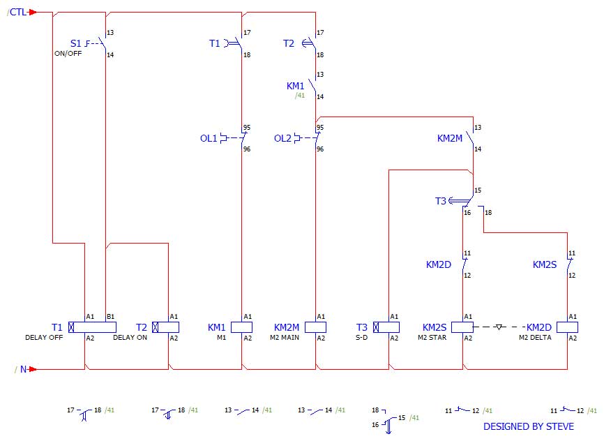
    As far as I can figure, it can't be done with only 2 timers. Three are required.

    Assuming there aren't safety considerations (i.e., its cat A), this is how I'd do it:

    264625.jpg


  • Registered Users Posts: 2,637 ✭✭✭brightspark


    Yes Steve it needs 3 timers, one for the star-delta and two for the control.

    What would you do regarding overloads?
    Should the overload stop both motors together, just the motor affected, or if the bigger motor allow the other motor to come to a timed stop?


    But perhaps I'm over thinking it, and there is no harm in stopping both together in trip and emergency situations.

    (Out of curiosity what software did you use to draw it?)


  • Moderators, Category Moderators, Entertainment Moderators, Sports Moderators Posts: 22,584 CMod ✭✭✭✭Steve


    Forgot about the overloads, I'll stick them in this evening and post back.

    As to the stopping sequence, it really depends on the equipments physical requirements but at a guess: OL1/KM1 trip should stop KM2, OL2/KM2 should just stop itself.

    Drawn with eplan.


  • Moderators, Category Moderators, Entertainment Moderators, Sports Moderators Posts: 22,584 CMod ✭✭✭✭Steve


    With overloads.

    6RFKnR.jpg


  • Advertisement
  • Registered Users Posts: 3 MP Maint


    Ok guys thanks to everyone for the response,

    The situation is a live show, all safety precautions and devices are in play.

    Steve what can I say only THANK YOU.


  • Closed Accounts Posts: 13,422 ✭✭✭✭Bruthal


    A relay wired with hold on, start and stop would give a non restart on power loss setup, instead of the on-off switch, possibly.


  • Moderators, Category Moderators, Entertainment Moderators, Sports Moderators Posts: 22,584 CMod ✭✭✭✭Steve


    MP Maint wrote: »
    Ok guys thanks to everyone for the response,

    The situation is a live show, all safety precautions and devices are in play.

    Steve what can I say only THANK YOU.
    If you're wiring this up, make sure you check the pinouts on your timers, contactors and overloads, they may not match the diagram I posted. Use the diagram at your own risk. :)
    Bruthal wrote: »
    A relay wired with hold on, start and stop would give a non restart on power loss setup, instead of the on-off switch, possibly.
    Yep, it would need a 2nd auxiliary contact on KM1 though, may not be there. Although a snap-on one could be added.

    Edit, just read your post again, a relay would of course work.


  • Closed Accounts Posts: 13,422 ✭✭✭✭Bruthal


    Probably wouldn't work properly using km1 aux. Pressing the stop button would need to be held to time out by the look of it. I could be looking at it arseways of course. Nothing unusual there :)


  • Moderators, Category Moderators, Entertainment Moderators, Sports Moderators Posts: 22,584 CMod ✭✭✭✭Steve


    Yeah, you're correct there, a separate relay would be needed with a contact where S1 is.


Advertisement