Advertisement
If you have a new account but are having problems posting or verifying your account, please email us on hello@boards.ie for help. Thanks :)
Hello all! Please ensure that you are posting a new thread or question in the appropriate forum. The Feedback forum is overwhelmed with questions that are having to be moved elsewhere. If you need help to verify your account contact hello@boards.ie

Single phase motor schematic

Options
  • 07-01-2015 7:21pm
    #1
    Registered Users Posts: 463 ✭✭


    Hi
    I've a single phase.55kw motor capacitor start capacitor run, I need it to run in both forward and reverse. Could someone post a schematic drawing for the power and control circuit, thanks in advance.


Comments

  • Closed Accounts Posts: 13,422 ✭✭✭✭Bruthal


    What you need to do is get both ends of the start winding, and reverse the connections, which can be achieved using contactors


  • Closed Accounts Posts: 13,422 ✭✭✭✭Bruthal


    Is this motor already up and running, or nothing done yet?

    Here is how a reversing setup can be connected to 2 contactors, or one contactor with 2 n/c and 2 n/o contacts, each with a n/o and n/c contact. Its only a rough idea, and there are more methods.
    6844735_orig.jpg

    It will only be a part of the overall power circuit, but gives an idea of the actual forward/reversing part for this particular setup.

    Top shows the start winding, which has had its ends disconnected from their original points so you now have an open circuit on each end of winding. Each end of winding connects to both the n/o and n/c contacts as shown, and the connections the winding was originally connected to go to the other side of the contactor contacts as shown.


  • Registered Users Posts: 463 ✭✭grousedogtom


    Nothing done yet


  • Closed Accounts Posts: 13,422 ✭✭✭✭Bruthal


    Nothing done yet

    Whats it going to be used for?


  • Closed Accounts Posts: 13,422 ✭✭✭✭Bruthal


    This one is better. Used the other one before on a project with DC motors.

    Your setup would be easier with this. Im using MS paint as I go along:D

    5370509_orig.jpg

    As with the earlier one, it is only part of the power circuit. When either the forward or reverse contactor is energised, they will also supply the motors main winding via more contacts.

    And there is the control circuit to add.


  • Advertisement
  • Registered Users Posts: 463 ✭✭grousedogtom


    Many thanks for all of the above information, it will be used for an automatic scraper in a cubicle farm shed, it's an old set up that is being fitted.


  • Closed Accounts Posts: 13,422 ✭✭✭✭Bruthal


    If you want a control circuit, I can draw something up for that too, as well as the rest of the power circuit.

    Its really like a dol starter circuit, but with a start for the forward, another for the reverse, and an overall stop button which stops which ever contactor is energised. Also the same as or very similar to a 3 phase forward/reverse control circuit.

    Each start button will incorporate a n/c contact from the other contactor in series with it, for electrical interlocking, so for example, the forward contactor wont close when the reverse one is energised.

    Are you familiar with any of that?


  • Registered Users Posts: 1,136 ✭✭✭maxamillius


    I wouldnt mind seeing that diagram bruthal just to refresh my memory on motor control?
    If it's not too much hassle?


  • Closed Accounts Posts: 13,422 ✭✭✭✭Bruthal


    I wouldnt mind seeing that diagram bruthal just to refresh my memory on motor control?
    If it's not too much hassle?

    I dont actualy have one on file, I will just sort of draw it from the mind, especially since a forward/reverse for a single phase motor might be slightly less common than for a 3 phase motor.

    As a matter of interest, forward/reverse for a universal motor would be very similar, reversing the connections to the actual brushes to reverse them.

    Control circuit would be practically the same though for single phase and 3 phase motor reversing.

    I will do one up tomorrow evening if I get a chance anyway. Might even use autocad to get it looking a bit less cartoon like:D


  • Registered Users Posts: 463 ✭✭grousedogtom


    Bruthal wrote: »
    If you want a control circuit, I can draw something up for that too, as well as the rest of the power circuit.

    Its really like a dol starter circuit, but with a start for the forward, another for the reverse, and an overall stop button which stops which ever contactor is energised. Also the same as or very similar to a 3 phase forward/reverse control circuit.

    Each start button will incorporate a n/c contact from the other contactor in series with it, for electrical interlocking, so for example, the forward contactor wont close when the reverse one is energised.

    Are you familiar with any of that?

    Yes it all makes sense, great information Brutal, if you can I'd appreciate the control circuit also, thanks again.


  • Advertisement
  • Closed Accounts Posts: 13,422 ✭✭✭✭Bruthal


    Yes it all makes sense, great information Brutal, if you can I'd appreciate the control circuit also, thanks again.

    Yes I will do something up tomorrow evening if I get a chance.


  • Closed Accounts Posts: 13,422 ✭✭✭✭Bruthal


    I assume you have access to both ends of the start winding, which will be needed for this, or there is a reversing method on the motor already?


  • Registered Users Posts: 463 ✭✭grousedogtom


    Yes I've access to both ends of the start winding.


  • Closed Accounts Posts: 13,422 ✭✭✭✭Bruthal


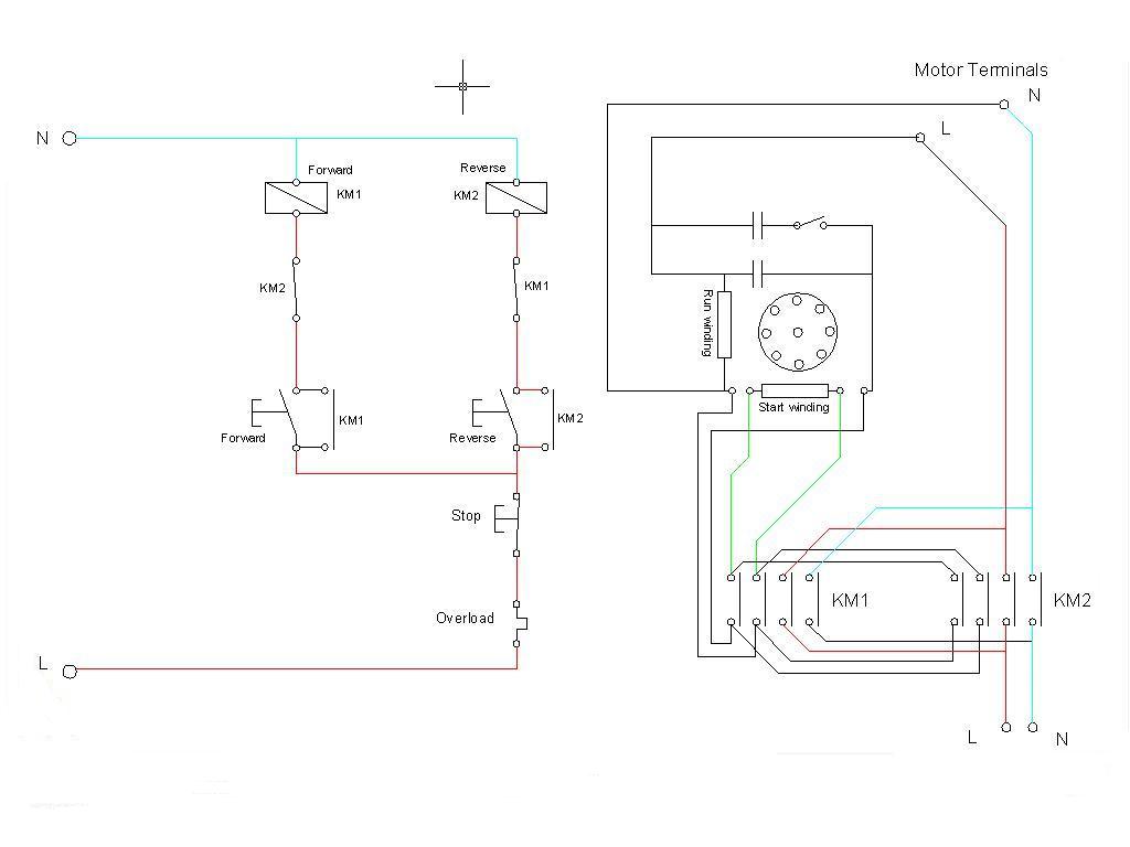
    Hopefully you can follow this. I drew it up from the head but it should work ok. Control circuit on left, power on right. Didnt bother with all terminal numbers.

    Its using 2 contactors which will need 4 n/o contacts each for the running of and reversing of the motor. And another n/o for the hold on contacts which are the ones in parallel with the forward and reverse push buttons.

    And 1 n/c contact on each then for the interlocking, which are the KM1 and km2 n/c contacts just above the forward and reverse buttons in the control side of the drawing. These 2 aux contacts per contactor (hold on and interlock) are only shown in the control circuit diagram.

    An overload is shown before the stop button, but if using them, both contactors will need them and then second overload in series with first but you probably wont bother for a small motor.

    Motor might be a little different than the one shown here, but the idea will be the same. Each contactor as well as deciding if the motor goes forward or reverse, also switches on the supply to the motor like a DOL starter.

    The switch in the motor after the capacitor is just the centrifugal switch that disconnects that capacitor when the motor is up to speed.

    L and N supply to the power circuit at bottom right can supply the control circuit as well. Maybe put a separate small fuse on the control circuit as well.
    168443_orig.jpg

    So the 2 contactors use 2 contacts to switch the mains supply to the motor so that whichever one closed, the motor gets L and N to it, and the other 2 contacts connect the start winding in one polarity or the other, depending on which contactor is closed.
    And 2 aux contacts, one n/c and one n/o to do the interlocking and hold on respectively.


  • Registered Users Posts: 463 ✭✭grousedogtom


    Great information and thanks for your time, it's all very clear, much appreciated


  • Closed Accounts Posts: 13,422 ✭✭✭✭Bruthal


    Let us know how you get on. Anything needs clarifying, ask away and I will try to answer.


  • Registered Users Posts: 463 ✭✭grousedogtom


    What's the least amount of cores in a cable this set up will work off from the control panel to the motor, there is a 6 by 2.5 in place as it is, can this work or will I need 7 core including the earth?


  • Closed Accounts Posts: 13,422 ✭✭✭✭Bruthal


    Yes 6 cores needed to the motor from the contactors. Plus an earth.

    Might be a good idea to test reversing the motor start winding to check it reverses. Just to ensure it is the start winding etc.


  • Closed Accounts Posts: 13,422 ✭✭✭✭Bruthal


    Did you ever try getting it going?


Advertisement