Advertisement
If you have a new account but are having problems posting or verifying your account, please email us on hello@boards.ie for help. Thanks :)
Hello all! Please ensure that you are posting a new thread or question in the appropriate forum. The Feedback forum is overwhelmed with questions that are having to be moved elsewhere. If you need help to verify your account contact hello@boards.ie

Monitor repair questions

  • 22-01-2015 6:39pm
    #1
    Registered Users, Registered Users 2 Posts: 1,931 ✭✭✭


    I have a Dell 2405FPW that went about a year ago. As far as I recall there the lights went out, there was a slight burning smell and a small bit of smoke. However, it was a while ago so I can't be sure of all that.

    Anyway, I finally got around to opening it and could only see two dodgy looking components, the resistor with the outer casing damage and a large 450v 120uf capacitor with the brown corrosion at one of the terminals. Both of these are pictured.

    I guess I'm wondering whether it's worth trying to replace one/both of these. I have a soldering iron and a multimeter, but I'm not very good with the soldering iron. However, there's a bit of space around these particular components. Are the pictured components likely dead or is it possible/probable the problem is elsewhere? The large capacitor looks fine other than at the terminal.


Comments

  • Registered Users, Registered Users 2 Posts: 368 ✭✭backboiler


    There's every chance that the problem is somewhere else, but these are cheap components. It's worth a euro or two and an hour of your time to give it a shot.


  • Registered Users, Registered Users 2 Posts: 1,931 ✭✭✭Zab


    Thanks backboiler. You're right, I was probably overthinking it. Although I guess I'm somewhat worried about breaking it even further.


  • Registered Users, Registered Users 2 Posts: 1,946 ✭✭✭whizbang


    I would put good money on the transistor on the heatsink next to the resistor. PFC? Also replace the diode there too.


  • Closed Accounts Posts: 8,657 ✭✭✭CountyHurler


    I have had similar ones to this... You need to work out the value of that resistor from the coloured lines (or bands) on it... The capacitor values will be easy to see on the side of it....

    I would also check the bridge rectifier and power mosfet that drives the transformer.. maybe check the secondary output diodes and electrolytic capacitors as well... The secondary side electrolytic capacitors are VERY prone to failure...

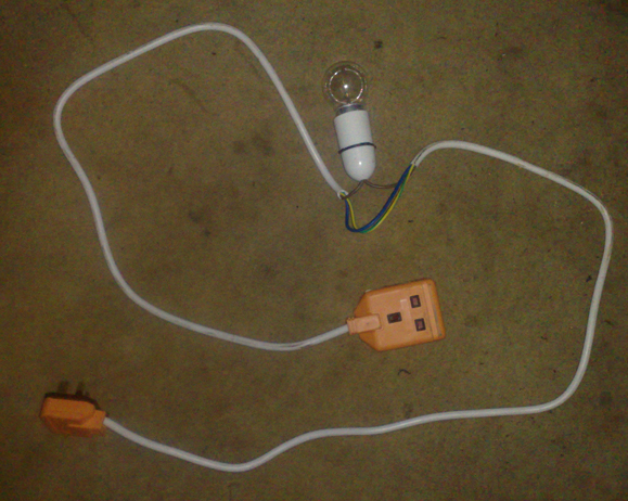
    Oh and when you have replaced the parts you are bad, it's best to use something like this.. My own variation on a dim bulb tester.. This is to limit the current in the circuit.. It allows you to ensure that there is not a short in the circuit before you plug it in to the mains... If the bulb comes on, then you may still have a short.. Google around "dim bulb tester" for more information..

    6pnnW2.jpg


  • Posts: 5,238 ✭✭✭ [Deleted User]


    My own variation on a dim bulb tester..

    :D
    Nice work.


  • Advertisement
  • Closed Accounts Posts: 8,657 ✭✭✭CountyHurler


    :D
    Nice work.

    I read Jestine Yong's book on SMPS and LCD Repair, and he takes out the fuse from the power board and solders a bulb across the fuse holder!! For a clever guy, I find this a mind numbingly cumbersome way of doing things...

    I also have a more advanced version where I have one of those small consumer units on the floor and wire the cables through a small ampage MCB and RCD...


  • Posts: 5,238 ✭✭✭ [Deleted User]


    I'd check the primary side isolated then I'd power the secondary off an external current limited supply for that sort of thing if it's possible.
    I'm gonna make me one of them phase testers though.


  • Registered Users, Registered Users 2 Posts: 1,931 ✭✭✭Zab


    whizbang wrote: »
    I would put good money on the transistor on the heatsink next to the resistor. PFC? Also replace the diode there too.


    Hmm, that looks more difficult to replace. You're talking about the silver heatsink at the left of the overview image and the black component that it's attached to (just replacing the component obviously)?

    I would also check the bridge rectifier and power mosfet that drives the transformer.. maybe check the secondary output diodes and electrolytic capacitors as well... The secondary side electrolytic capacitors are VERY prone to failure...

    ... Google around "dim bulb tester" for more information...

    Okay, I'll look into identifying and replacing these components, although again my soldering skills aren't great. This is making it hard to work out which components to try first though.

    I'll put together a dim bulb tester, however. I even have all the components already. Thanks!


  • Posts: 5,238 ✭✭✭ [Deleted User]


    Zab wrote: »
    .... (just replacing the component obviously)?

    Okay, I'll look into identifying and replacing these components,

    I'd recommend testing them first. Diagnostics is not just part swapping until you get it right.

    The bridge rectifier and MOSFET can be tested with a DMM looking for reversed biased resistance/continuity. Then another test of the mosfet is to check the Drain-Source path when the Gate-Source is High.

    Some components you can test on the board (bridge rectifier) others (MOSFET, resistor) you may have to desolder and check isolated as other passive components may interfere with your results.


  • Closed Accounts Posts: 8,657 ✭✭✭CountyHurler


    I'd recommend testing them first. Diagnostics is not just part swapping until you get it right.

    Yeah, I wouldnt just "chance" plugging it in after replacing the parts.... You could end up replacing the same parts again, and possibly other components as well!

    If it was mine I would....
    1. Check for continuity along the path from the input L and N pins to the centre pins of the bridge rectifier.. (to make sure no coils or fuses have blown).
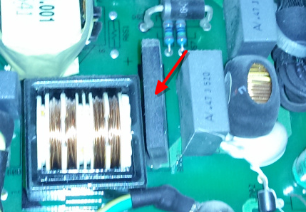
    2. Make sure the bridge rectifier is not shorted.. You can also check voltage drop across the four internal diodes. That's the BR below.
    7ZbwsY.jpg
    3. With the new components in place, I quickly move around the circuit making sure that there are no shorts...
    4. Plug the device in to the dim bulb tester and power on


  • Advertisement
Advertisement