Advertisement
If you have a new account but are having problems posting or verifying your account, please email us on hello@boards.ie for help. Thanks :)
Hello all! Please ensure that you are posting a new thread or question in the appropriate forum. The Feedback forum is overwhelmed with questions that are having to be moved elsewhere. If you need help to verify your account contact hello@boards.ie

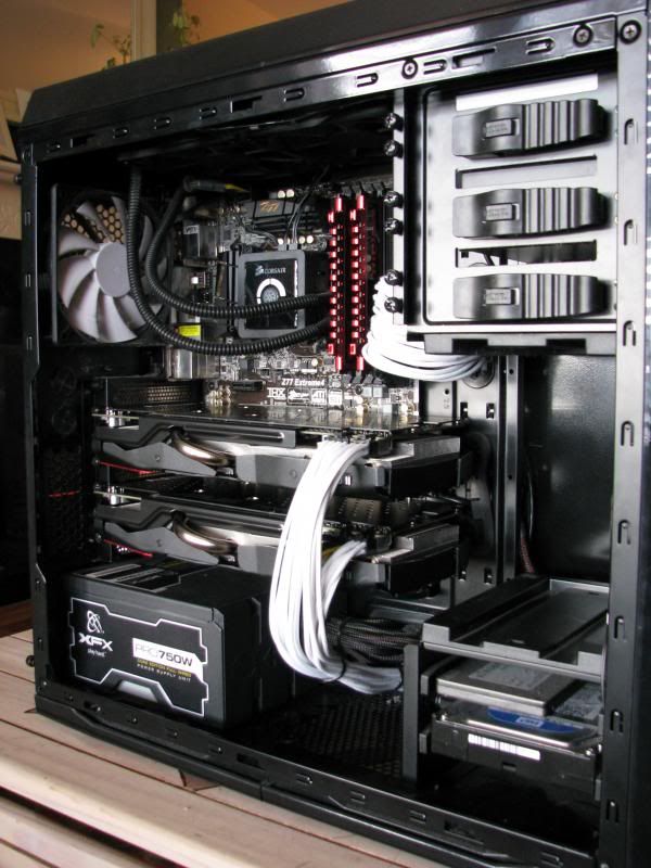
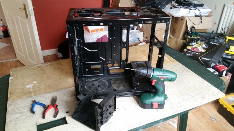
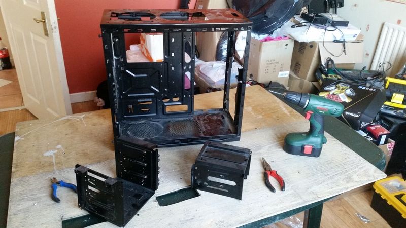
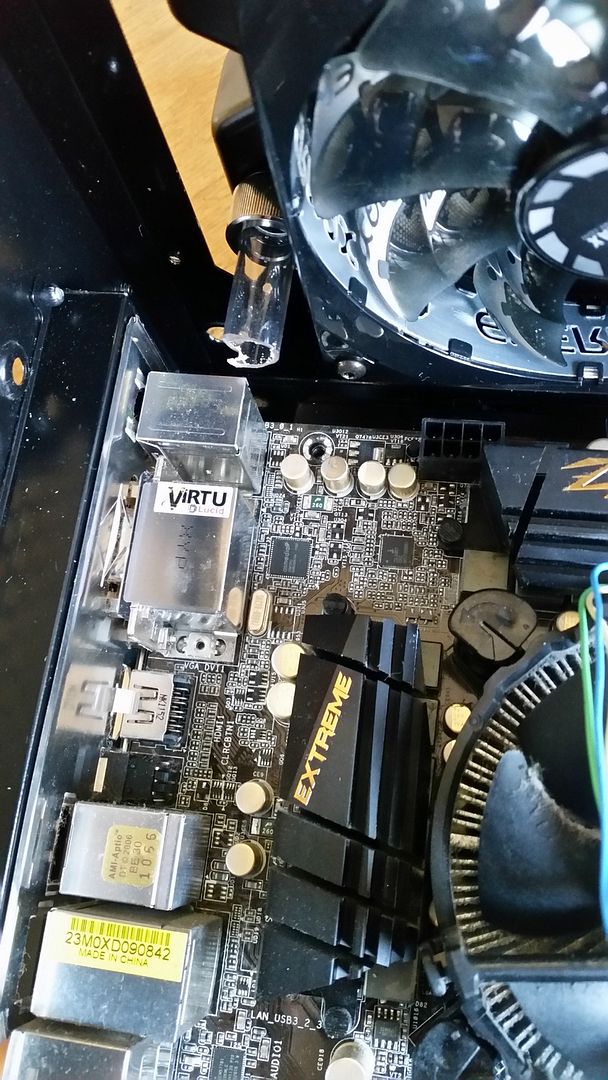
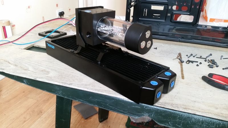
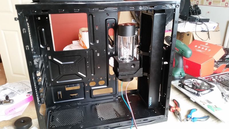
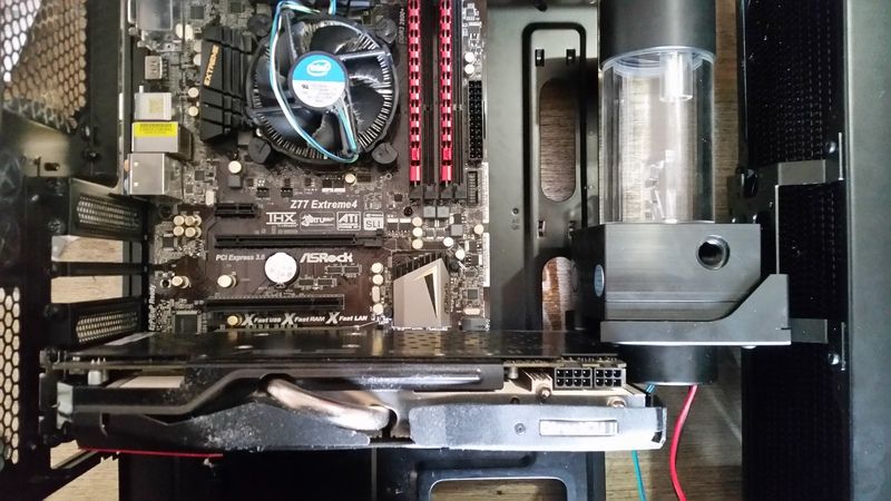
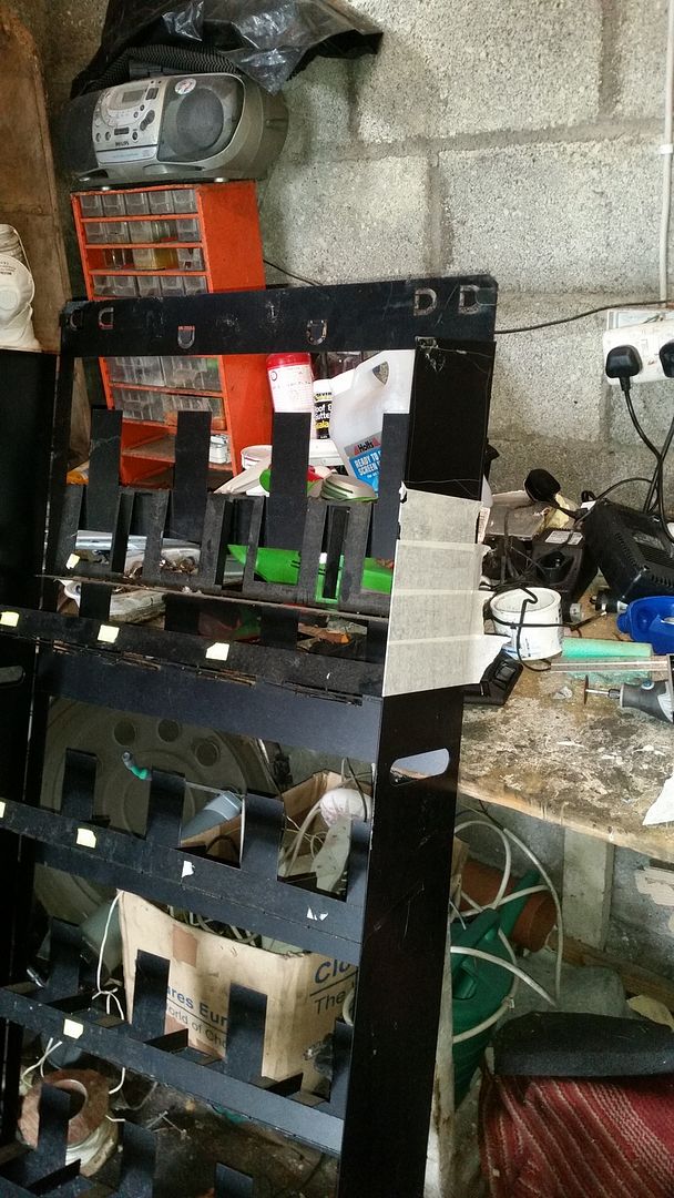
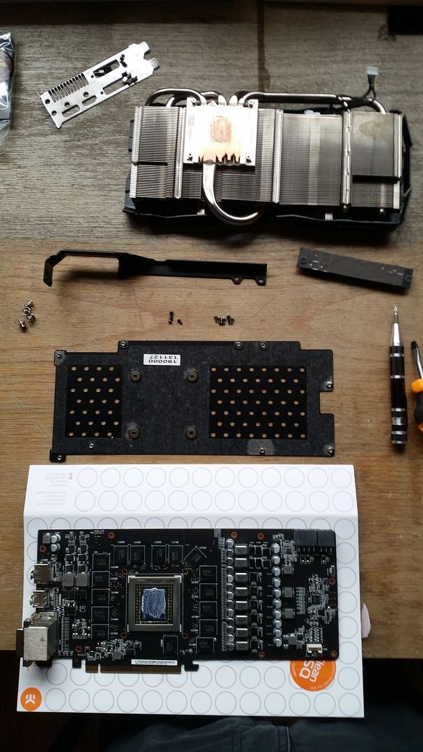
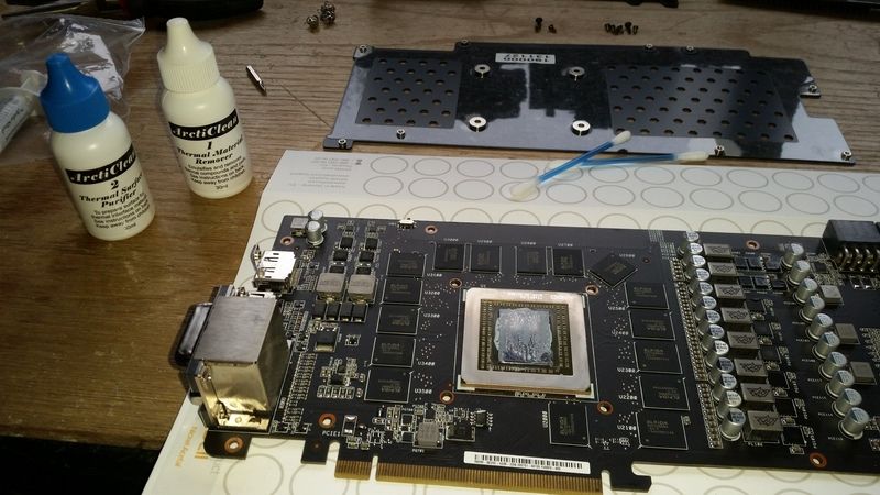
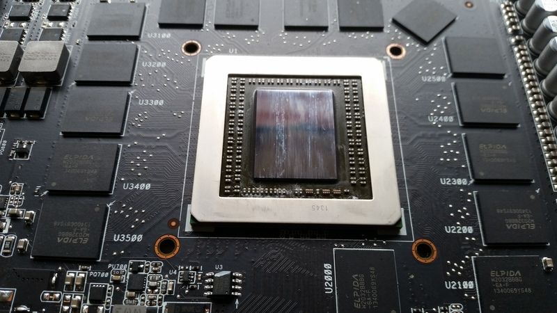
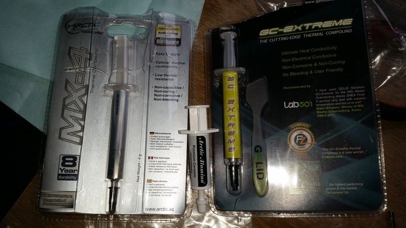
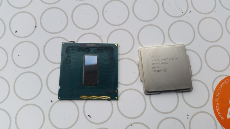
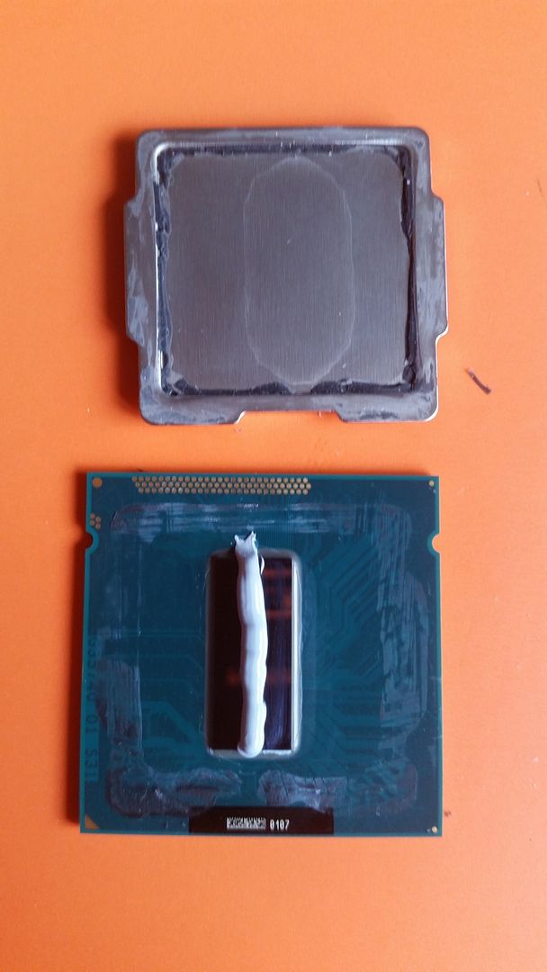
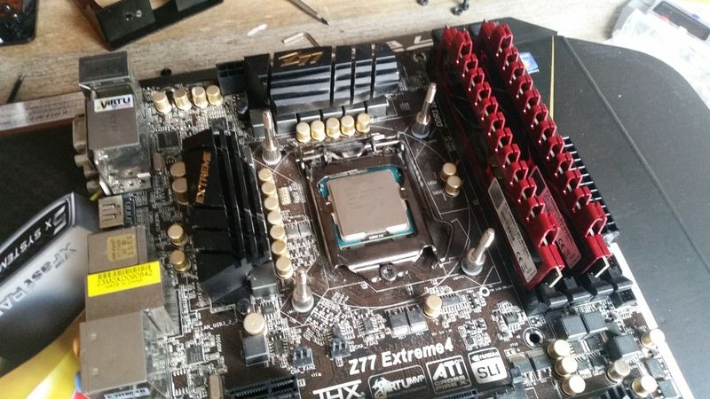
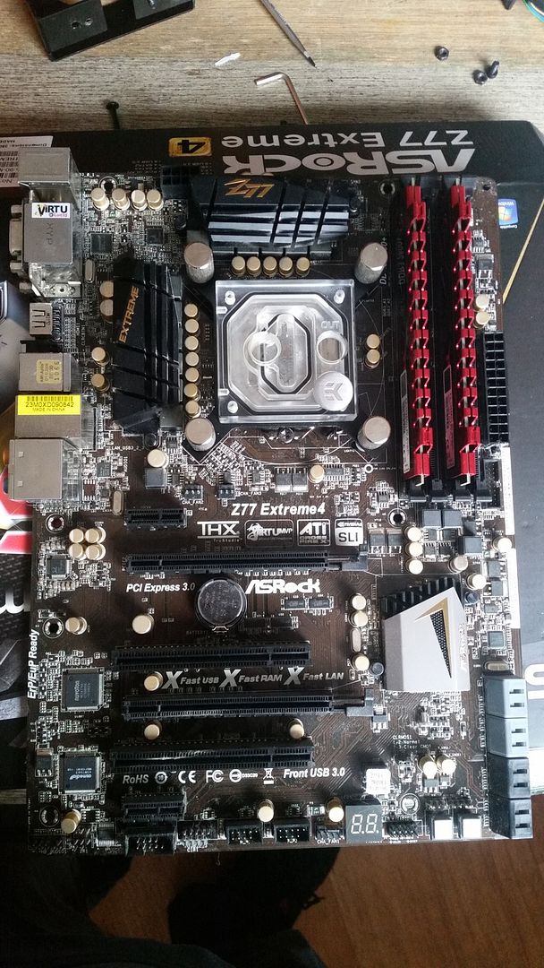
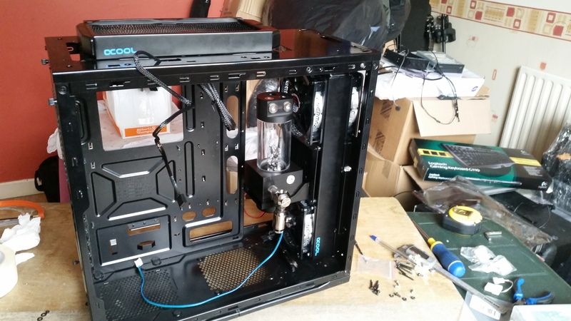
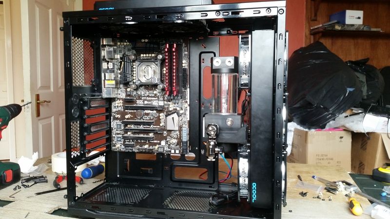
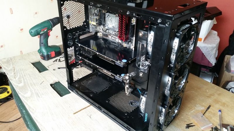
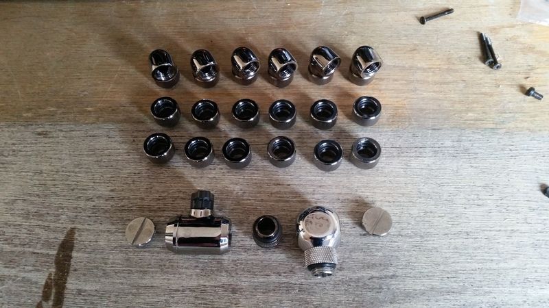
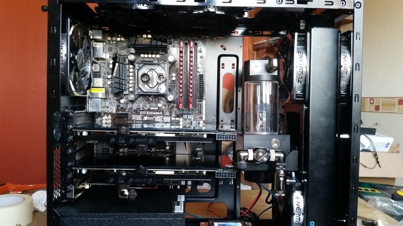
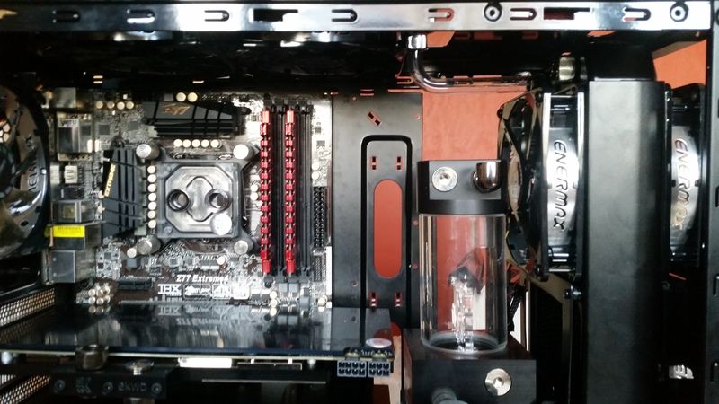
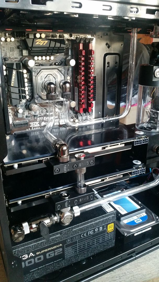
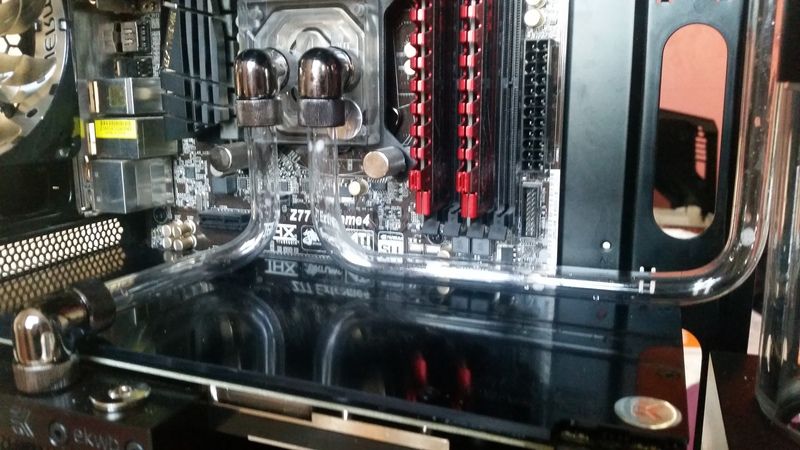
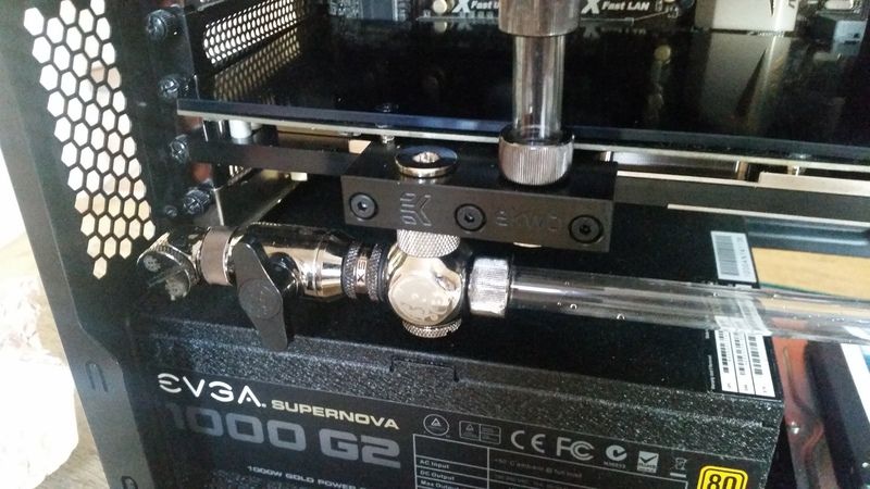
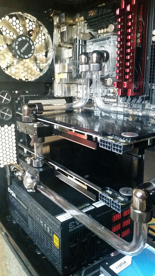
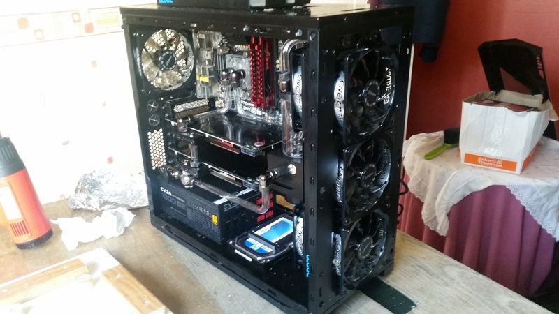
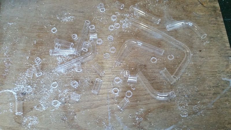
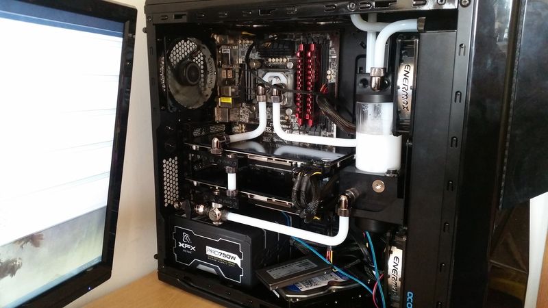
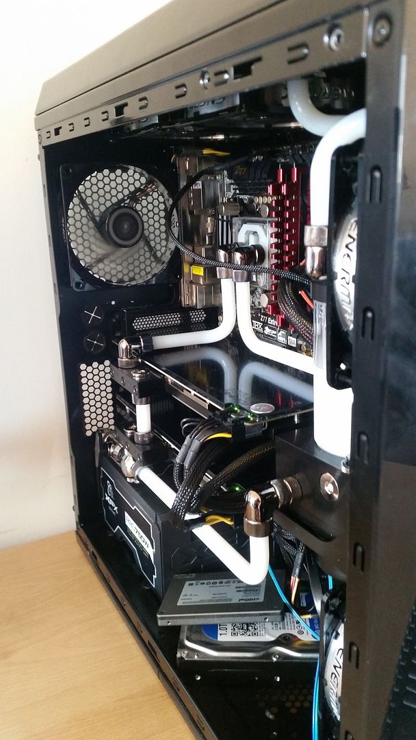
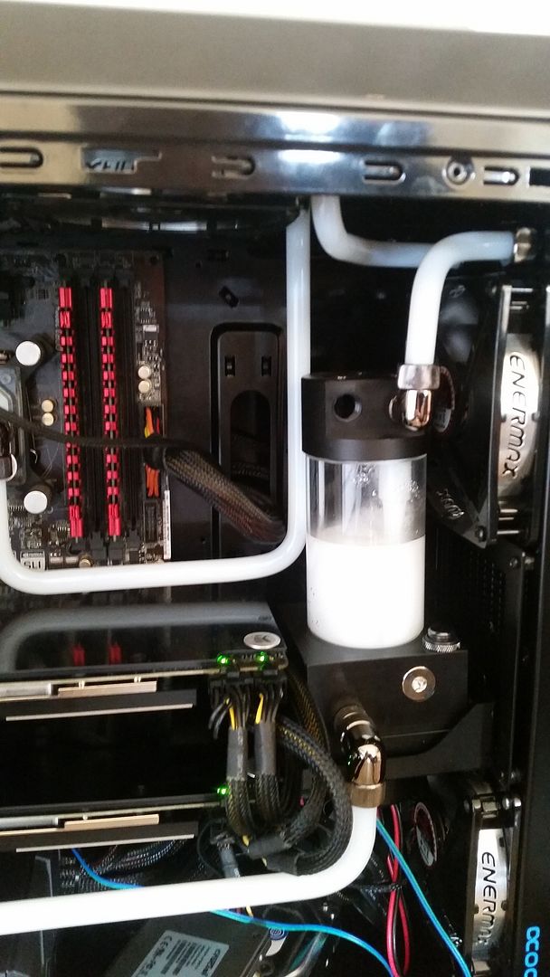
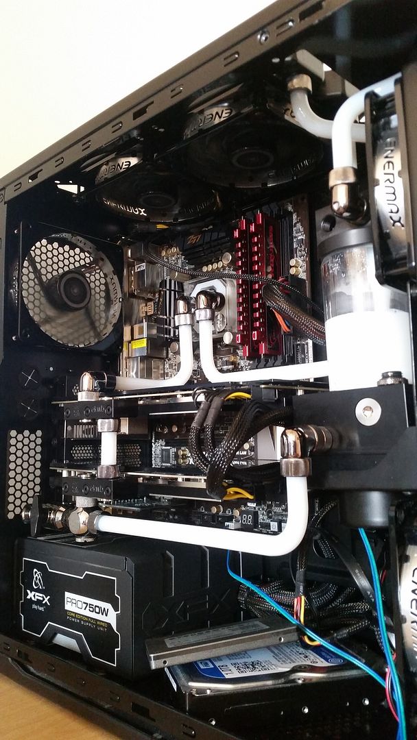
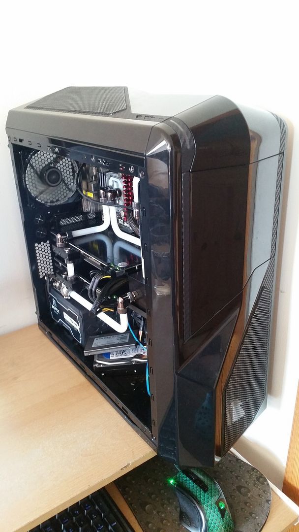
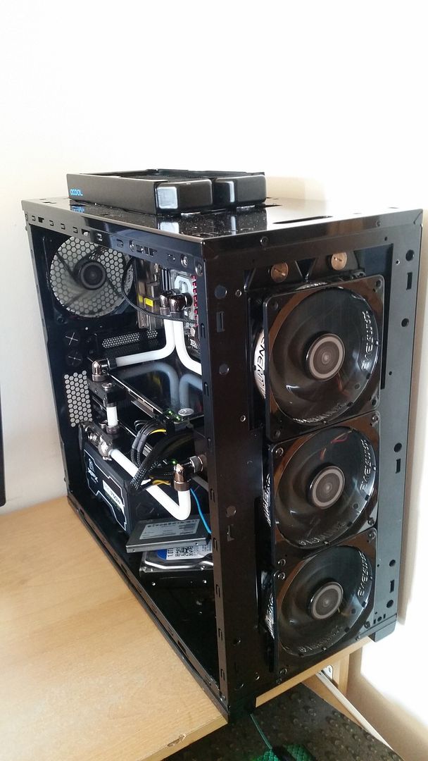
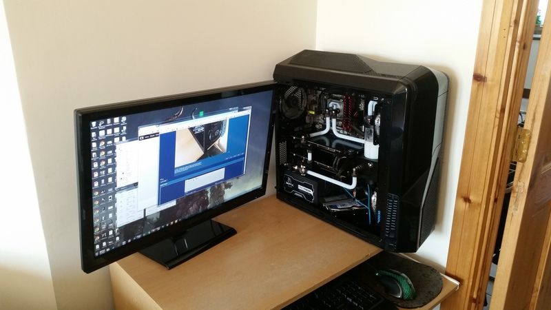
BUILD LOG: Modded NZXT Phantom 410, Acrylic Loop, OC'd 3570k, R9 290 xFire

Options
  • 01-04-2015 12:54am
    #1
    Registered Users Posts: 1,259 ✭✭✭


    So after 13 months of planning, getting married, having a baby,starting a new job and a move to another town, I have finally broke ground on a case mod and watercooling project I have had in the pipe works for far too long! The plan is to upgrade my watercool my current system as the 290s are far too hot, I need to set the GPU fans to 100% via Afterburner and turn all 7 case fans up to 12v just to maintain temps of high 80s! Some games reach 94c where my cards start to thermally throttle by up to 20%.

    Could I have done this cheaper and easier? Certainly, but where is the fun in that?! :P

    This is how she stands today;

    IMG_1145.jpg

    The only difference is I have an EVGA Supernova G2 1000w PSU in there now instead of the XFX 750w.

    The vital stats,

    3570k.
    Two Asus r9 290's in crossfire.
    Both currently stock clocks as on stock cooling but I had the CPU OC'd to 4.5ghz for the better part of a year and a half until my H100 died a while back.
    A black NZXT Phantom 410.

    Into which I plan to fit two radiators.

    A 30mm thick 240mm Alphacool NexXxoS ST30 on top.
    And a 45mm thick 360mm Alphacool NexXxoS XT45 in the front.

    To fit the front rad I will be removing the lower HDD cage and the 5.25" drive bays on top.
    The 240mm rad on top will be configured push and the 360 in front will be push pull. To which I will add 9 Enermax TB Silence PWM fans. 8 for the rads (actually 7 for the rads, more on that later, and one as a stand alone exhaust.

    I have an EK Xres 140 D5 PWM pump and res combo which will be mounted onto the back of the 360mm rad and a pair of EK blocks for both the 290's and an EK Supremacy CPU block (tips hat to Serephucus :cool:).

    The pump and all fans will be PWM controlled (hopefully) via a custom made 10 way PWM splitter PCB I managed to get off some guy in the UK. He made a handful as a project and flogged em on eBay afterwards.

    I plan to delid the 3570k also and originally had planned a full set of custom cables but I'm not 100% on that at the mo cause I dunno if I can be arsed tbh! Oh, there'll also be an obligatorey window mod to follow as well!

    So, without further adieu, onto the nitty gritty of ot all!

    I spent a few hours at today, stripping down to old build test fitting a few pieces and have already hit several snags. Details in the pics below.

    Stage one, after stipping down the existing build I set to work on those useless 5.25" bays. A few minutes work with a drill and a long nose pliers and those rivets are outta there.

    20150331_151210.jpg


    Followed shortly thereafter by the HDD cage below.

    20150331_151702.jpg


    Now to test fit a few pieces. My first concern was having the radiator ports from the 240 rad on top, at the back of the case. I thought there would be clearence issues with motherboard heatsinks or the I/O panel.

    20150331_160348.jpg


    Luckily however, there is not. It only fits by a couple of millimetres, but it's plenty!

    20150331_160452.jpg


    Next job was to assemble the pump. I have a multi port top, additional mounting brackets and a dress up kit to install.

    20150331_161530.jpg


    The additional pump cover tidies everything up nicely.

    20150331_163825.jpg

    20150331_164358.jpg

    20150331_164413.jpg

    So the first snag I hit was the additional mounting plate I bought from EK so I could mount the pump and res vertically on the back of the radiator is drilled for 4mm bolts. The tapped holes on the rads are only 3mm so they had to be widened.

    20150331_170410.jpg

    I tried to get all engineery and use the tap and die set I bought from Aldi for €20 to tap 4mm threads into the newly widened holes.

    20150331_170504.jpg


    And proceeded to drop the tap handle directly onto the rad and damage some of the fins! :o

    20150331_173302.jpg


Comments

  • Registered Users Posts: 1,259 ✭✭✭..Brian..


    The pump wit all the accessories fully assembled and mounted to the rad. Looks like some sort of future tank!

    20150331_174607.jpg


    Or maybe some sort of laser cannon, I can't decide!

    20150331_174619.jpg


    But at last, here she is installed into the case. Looks pretty sweet!

    20150331_175109.jpg


    My chuffedness is short lived however as we have just hit snag number two. The GPUs will not fit with the above config. The PCB is about 5mm too long. ****.

    20150331_175335.jpg

    I suspected I may have had trouble here which is why the 360 rad is not fully push pull. I will be leaving off the middle pull fan to make way for the res. But look at all that wasted space behind the bracket between the res and the rad. There must be 20mm in there easily. I decided I would have to scrap the bracket and try make something myself so I called out to my Dads and had a route around his garage and found this. Not sure what it is, a cassette tape display for a shop maybe but it's 1.5mm steel and black, happy days! I taped off a section and marked out a 120x120mm square.

    20150331_182249_1.jpg


    Time to break out the Dremmel!

    20150331_182553.jpg


    Slowly but surely, getting there.

    20150331_183401.jpg


    And it's free!

    20150331_184050.jpg


    A hacksaw made light work of the remaining side. So much faster than the Dremmel it's hard to believe!

    20150331_184334.jpg


    Now to straighten out those edges. I just took my time, teasing my way up to the line.

    20150331_185136.jpg


    With the edges straightened out, I clamped the EK bracket onto my work piece to use as a template to make out the holes. As some of my woodworking friends always say, "You can never have enough clamps!"

    20150331_190408.jpg


    Again using the original part as a template and marking out the holes for the pump holder.

    20150331_191244.jpg

    20150331_191252.jpg


    All holes drilled.

    20150331_191739.jpg


    Now to mark out interior to be removed and come up with some sort of design.

    20150331_192510.jpg


  • Registered Users Posts: 1,259 ✭✭✭..Brian..


    With the design drawn out, I drilled a few 8mm holes to try and make space to get the hacksaw blade in there to start removing the waste.

    20150331_193031.jpg

    Most of the material has been removed here by now. To get tight down to the line, I just cut a series of shallow cuts at then came at them sideways to clear them out. It worked out quite well.

    20150331_195009.jpg

    20150331_195658.jpg

    20150331_200500.jpg


    And then the filing began. And went on and on and on for about an hour!

    20150331_202508.jpg


    Finally here we are, not bad for a fella with no experience in metal fabrication and only hand tools! I'm not sure on the curves though, I thought they might look nice but I think I'm just gonna square them off tomorrow. I also need to square up a few places and then sand it all down and give it a spray paint, but for a bracket that will be difficult to see, I think it will do nicely.

    20150331_202523.jpg


    And finally an obligatory beer! More to follow tomorrow, cheers!

    20150331_212452.jpg


  • Registered Users Posts: 1,259 ✭✭✭..Brian..


    So haven't had a chance to get a lot of work done recently, real life getting in the way etc but I'm making some progress!

    Also did anyone else know you can only upload 15 pictures per post? Kinda annoying!

    Anyway, onto the build.

    Day 2:

    So day two started where day one left off, filing!

    20150401_120255.jpg


    As I mentioned earlier, I didn't really like the curves on the bracket I was making so I decided to square them off. I just cut down with the hacksaw and used a worn dremmel cutting disc to cut out the bottom pieces.

    20150401_120439.jpg

    Followed by more filing ...

    20150401_120958.jpg

    And the final shape starts to come together.

    20150401_120642.jpg

    Unfortunately I got a bit carried away with the filing and you can see one of the centre holes is very close to the edge, we'll have to wait and see how that turns out.

    20150401_121838.jpg


    After all the filing it was time to try out a bit of sanding. Here I have an 80 grit sanding attachment for the drill which I used to debur all the edges and holes.

    20150401_121914.jpg

    Followed by some hand sanding at 120 grit.

    20150401_122557.jpg

    And here it is, ready for it's first coat of paint.

    20150401_123009.jpg

    20150401_124010.jpg

    Here's how it turned out after the first coat. I managed to smudge some TIM into as I was test fitting pieces but I will be sanding and adding another coat later.

    20150401_160248.jpg


    However we've hit another snag. The centre holes are out by a couple of mill in relation to the pump holder. Plus the issue with the hole being so close to the edge I thought I would have to start over.

    20150401_161053.jpg

    But I decided to try clamping the two pieces together and drilling new holes through both at the same time, at least that way I would know they would definitely line up.

    20150401_162818.jpg

    Et voila! Everything lines up and fits together correctly. And a little sneak preview of the drainage system, subject to change of course!

    20150401_171214.jpg


  • Registered Users Posts: 1,259 ✭✭✭..Brian..


    So the next job I tackled was installing the blocks and back plates on the GPUS.

    20150401_133200.jpg


    Opps, there goes my warranty!

    20150401_133700.jpg

    20150401_133653.jpg


    But four screws later, the stock cooler was off.

    20150401_133854.jpg


    Getting the end plate off was a bit tricker but the long nose pliers made another appearence and saved the day.

    20150401_134201.jpg


    But the stock coolers did not come off as cleanly as I had first thought. The four screw holding the stock cooler onto the PCB are connected to standoffs, just like the ones you use to connect your mobo to your case. One of the standoffs had unscrewed from the cooler but was stuck to the screw which was going through the PCB.

    20150401_134743.jpg


    And then to make matters worse, the screw head stripped out on me!

    20150401_134727.jpg


    I tired every tool I had to hand but was unable to get any purchase. I futzed around with it for ages before admitting defeat and having to resort to more extreme measures. Yup, Dremmel time again!

    20150401_134945.jpg


    I cut a channel into the screw head as deep as I dared go, but it was enough to get a flat head screwdriver in there. I had to hold the standoff on one side with the pliers and jam the flat head screw driver in for the other side. After a couple of failed attempts and a lot of cursing, we finally made progress and the offending article was removed!

    20150401_135110.jpg

    20150401_135432.jpg


    And here's the whole card disassembled.

    20150401_140039.jpg


    I used some Articlean TIM remover which made short work of cleaning up the die.

    20150401_142345.jpg


    However, one of the GPUs had these striations left over that I couldn't get rid off, not sure what it is, haven't seen it before.

    20150401_142958.jpg


    Time to apply new TIM. I ended up going with GC Extreme. And then it was a simple matter of applying all the thermal pads to the memory etc.

    20150401_143412.jpg

    20150401_145157.jpg


  • Registered Users Posts: 1,259 ✭✭✭..Brian..


    A bit of reassembly and we're done!

    20150401_145535.jpg

    20150401_154959.jpg


    Seems like a waste to have all this kit left over just sitting in a box!

    20150401_155537.jpg


    And here we are again with more test fitting. I've had to change the orientation of the front rad, placing it with the ports on top instead of on the bottom as I originally planned, simply because it won't fit the other way. And because of that, I decided to spin the top rad around so the ports are at the front as well, just to make the loop cleaner.

    I've noticed that with the new bracket I made for the res, I actually can't fit a fan in the pull position on the rad. It's no big deal though, I'll just make some 5mm spacers and we should be in buisness.

    After that, I need to cut a piece of metal out off the front of the case to fit a fan on the rad where the 5.25" bays were, delid the 3570k, mount the waterblock onto that and then I should be able to get everything installed back into the case and start working on the loop!

    20150401_173743.jpg


  • Advertisement
  • Registered Users Posts: 1,259 ✭✭✭..Brian..


    Day 3

    Got a couple of hours in the other day but unfortunately most of it was spent in the car, driving out to the PC, taking measurements, driving into town, getting parts, driving back out etc etc.

    I needed to make some sort of spacer to raise the home made pump holding bracket off the radiator so I would have sufficent clearance for a fan between the res and rad. I figured about 5mm should do it so set off to the my local hardware store and picked up a few things.

    I originally was thinking some small diameter steel tube that I could cut down to size for the spacers but they didn't have any so I ended up getting a load of washers and some bolts also.

    20150404_143600.jpg


    By stacking the washers on top of each other I was able to attain the clearance I was looking for.

    20150404_151503.jpg

    20150404_151339.jpg


    Then it was time to take it all apart again for paint. I must have assembled and disassembled this one component about 20 times by now!

    20150404_152745.jpg

    20150404_152816.jpg

    About an hour later it was time to flip em all over to do the other side. After that I left them over night.

    20150404_162646.jpg


    Now the next job to tackle was to installed the CPU block.

    Ugg, stock!

    20150404_163017.jpg

    But not for long!

    20150404_163029.jpg


    Before I installed the new block, I decided to delid the processor. I know this is a well documented method but all the same I was like, "Am I seriously gonna hit my CPU with a hammer?!" :eek:

    20150404_163818.jpg


    Yes, yes I was! And three firm knocks later, the heat spreader is free without any damage, phew!

    20150404_163846.jpg

    I even bunched up some overalls behind the PCB in case it went flying but I needed have, the PCB burried into the wood!

    20150404_163903.jpg


    The Articlean made another appearance and made short work of the old TIM.

    20150404_164306.jpg

    20150404_165348.jpg


    And then to apply new TIM. For anybody curious, this is WAY too much TIM. I took the block off again afterwards to check how it had spread out and it was everywhere. I reapplied in the same way but only using half the TIM.

    20150404_165752.jpg


  • Registered Users Posts: 1,259 ✭✭✭..Brian..


    And then it was just a matter of installed the backplate onto the mobo and putting it all back together.

    20150404_171748.jpg

    20150404_172201.jpg

    And that was it for Day 3. More to come shortly!


  • Registered Users Posts: 1,259 ✭✭✭..Brian..


    Day 4

    So day 4 began by checking in on our newly blackened hardware. I found a stack of 6 washers to be the magic number. I made an extra set, just in case! Turned out well! The bracket looks a bit of a mess after the misaligned holes but it's all square when in place and all the holes are hidden so it's all good!

    20150405_122114.jpg


    Back to the case. This crossbar is just below the 5.25" drive bays and is in the way if I want to put a fan in there.

    20150405_123901.jpg

    The Dremmel made very short work of it.

    20150405_124823.jpg


    And a quick file down and blast of paint tidies it up nicely.

    20150405_125237.jpg


    The next snag I hit was I ran out of screws to connect the fans. And it being Easter weekend, no where will be open for two days. **** that! I have a load of very short screws, 10mm and less so let's make use of them!

    I tried connecting the fans with short screws from the inside holes but wasn't able to get the screwdriver in at them. So I widened the 4mm holes to 6mm with my drill.

    20150405_133749.jpg

    20150405_133801.jpg


    Even then the screws were only 10mm long, they were still too long. So I clamped them in a vice and took the Dremmel to them to take about a third off the length.

    20150405_134901.jpg


    Back in and after a bit of reassembly, now we're getting somewhere!

    20150405_141251.jpg

    20150405_141304.jpg

    20150405_143036.jpg

    20150405_143632.jpg


    Fittings. I am actually one push in fitting short for my original plan. I wanted to connect the GPUs in parallel but have settled for connecting them in series as I don't have the patience to wait for one fitting to arrive in the post!

    20150405_145056.jpg


    The layout of the loop is totally different than I had planned due to changing the orientation of the rads. So I spent a good while trying out a few different options and think I'm good to go.

    Not sure how effective the drain port will be here, it's directly after them pump so I should get a good amount out but the GPU is lower so I may have to drain the separately. May have to revisit this later.

    20150405_152659.jpg


  • Registered Users Posts: 1,259 ✭✭✭..Brian..


    The next job is to build a jig for bending the pipes. Back out to the garage to find some off cuts.

    20150405_153806.jpg

    20150405_155136.jpg


    Making sure everything is square.

    20150405_155242.jpg


    I was wondering what I was going to use for the round part and what sort of diameter I wanted for it. I lucked out and found an old wooden curtain railing in the garage that was perfect. I used the tubing itself to space it out.

    20150405_160139.jpg

    20150405_161120.jpg


    At last, tube bending time!

    20150405_162756.jpg


    I ****ed up the first tube trying a long run for the front the loop but luckily had enough left over to do a short run at the back.

    The jig is working great, very happy with it. It creates nice, tight bends accurately at 90 degrees. and A bit more practice and we'll be flying I reckon!

    20150405_164934.jpg

    20150405_164941.jpg


    And alas, I had to leave it there for the day! Just as I was getting into it but that's life. Dunno if I'll be able to get away to do some more work tomorrow but will update again ASAP.

    And don't be shy guys, comments, questions or opinions are more than welcome! :D


  • Registered Users Posts: 712 ✭✭✭deejer


    Looking good. Tidy.

    Just wondering what tubing you are using. Nice idea with the jig also.


  • Advertisement
  • Registered Users Posts: 1,259 ✭✭✭..Brian..


    Thanks dude, yea the jig worked out better that I had hoped! I'm using E22 tubing, 10/12mm. You can get 5m for about €25 which is about the best price I could find. The tubing on OCUK is really expensive (like everything else on their site). You can find it Here.


  • Registered Users Posts: 7,180 ✭✭✭Serephucus


    Looks fantastic. Can't wait to see how this turns out. :)


  • Registered Users Posts: 536 ✭✭✭Blitz17


    Looks great so far. I'd use CLP/CLU on the die instead of regular paste, since you went to the trouble of delidding.


  • Registered Users Posts: 1,259 ✭✭✭..Brian..


    Thanks guys, have a bit more work done today, more to do after dinner and will have a few pics up then!
    Blitz17 wrote: »
    Looks great so far. I'd use CLP/CLU on the die instead of regular paste, since you went to the trouble of delidding.

    Yea I was reading about coollabs stuff a couple of months ago and decided I was going to go with it but to be completely honest, I forgot all about until you just mentioned it!


  • Registered Users Posts: 1,259 ✭✭✭..Brian..


    Day 5

    So Day 5 began by getting stuck into some pipe bending. Again, this jig is making life a lot easier!

    20150406_142158.jpg


    Here's a failed attempt at bending on two planes. The tube creased a little bit.

    20150406_144234.jpg

    20150406_145221.jpg


    I found cutting the tube to lenght to be a bit of a pain in the hole so decided to add a little something extra to the jig. Back to the shed to find some more off cuts!

    20150406_145915.jpg


    A few minutes later and we have a nice secure tube holder!

    20150406_150638.jpg


    It allows for some really accurate and small incremental cuts, ideal for trying to tease the tube down to the correct length for a sung fit.

    20150406_150906.jpg


    So I wasn't happy with where the drain was before and after a bit more poking about, I have relocated it over under the GPU. I had a spare 90° fitting so might as well make use of it!

    20150406_175006.jpg

    20150406_175033.jpg


    A couple of bends in place up in the top right.

    20150406_175041.jpg


    First attempt at a second bend.

    20150406_180621.jpg


    And another tube in place.

    20150406_202407.jpg


    And one final addition to the jig, a ruler along the left guide.

    20150407_171419.jpg


  • Registered Users Posts: 1,259 ✭✭✭..Brian..


    Working on another run. The loop layout had been changed quite dramatically from concept by this stage but I'm very happy with the results. I started filling it at this stage but tbh, I was getting leaks left, right and centre so had to put down my phone! Nothing major, some fittings not as tight as they should be, some tubes not pushed far enough into the compression fittings to make a seal and quite embarrassingly, I forgot to plug one of the outlets on the pump! :eek:

    Luckily I had taken the necessary precautions so nothing was damaged.

    Here's a load of pics in it's current state. Loop complete but not filled.

    20150407_191127.jpg

    20150407_191135.jpg

    20150407_191156.jpg

    20150407_191210.jpg

    20150407_191219.jpg

    20150407_191231.jpg

    20150407_191239.jpg

    20150407_191258.jpg


    And all the off cuts and rejects!

    20150407_191530.jpg


    Finally for this update, I'm not sure if I'm having an issue with the pump or not. The flow rate seems very slow. It is the PWM version but I'd imagine that it would be like PWM fans are run full tilt when connected direct to 12v power supply? It's like it's only pumping at 10% power. I left it running for about 20 minutes and there was a small bit of improvement b nothing like I was expecting.

    Check out the clip below and let me know what you think. I've sent a ticket to EK re the same.

    https://www.youtube.com/watch?v=mFuZ6NpYpHA


  • Registered Users Posts: 536 ✭✭✭Blitz17


    Do you have the 4 pin coming from the D5 connected to a PWM header on the mobo/fan controller ?


  • Registered Users Posts: 1,259 ✭✭✭..Brian..


    Blitz17 wrote: »
    Do you have the 4 pin coming from the D5 connected to a PWM header on the mobo/fan controller ?

    Not in that clip but I did try it and it didn't seem to make any difference. There's no power to the mobo at present either.

    Been watching a few clips on YouTube and the flow rate is definitely very low.


  • Registered Users Posts: 536 ✭✭✭Blitz17


    ..Brian.. wrote: »
    Not in that clip but I did try it and it didn't seem to make any difference. There's no power to the mobo at present either.

    Been watching a few clips on YouTube and the flow rate is definitely very low.

    PWM headers can be adjusted in the BIOS menu , might be worth looking at.


  • Closed Accounts Posts: 29,930 ✭✭✭✭TerrorFirmer


    One of the finest jobs to appear on this forum. Well done! Following it with interest.


  • Advertisement
  • Registered Users Posts: 2,624 ✭✭✭Thor


    Loving the amount of work involved. The more effort seems to mostly lead to a better build I find, and definitely looks to be the case for you.

    Looking forward to the finished product.

    As for the flow, it does seem fairly slow and has me like everyone thinking a power issue. Can you try the pump on the MB pwm with the bios set to full speed.


  • Registered Users Posts: 1,259 ✭✭✭..Brian..


    Thanks guys, that's great feedback! It has been a lot of work alright but I think once it's up and running it will surely be worth it!

    I'm going out to check on it in about an hour, it's been running for the night. If there's no leaks I'll finish reassembly and have a route in BIOS to see if I can sort out the pump. I was hoping Ek would be on the ball replying to me so of there was an issue I wouldn't have to tear down the entire thing again!


  • Registered Users Posts: 1,259 ✭✭✭..Brian..


    Initial temps are astonishing! Rough idea would be about 20°C drop on the CPU and a 40°C (yes FORTY!!) drop on the GPU's! Haven't really got into it tho, just had a quick look, more interested getting the pump to behave.

    However it's not all good news, my PSU seems to have died, when I try to turn it on the fans spins for half a second, it clicks, and then shuts down. I tested it with a PSU tester and it failed. Have emailed EVGA, awaiting response. Luckily I still have that XFX 750w lying around so we're running but it means I can't get stuck into serious overclocking as I'm pushing the limits of the 750w with two 290s and a 3570k to OC!

    The pump issue seems to be be resolved. I have it connected to the CPU fan header and when I manually set it to max it flows nicely. The only prob is that all the fans are connected to it as well and they run full tilt too! Must come up with a way of separating them.

    No pics as no real visual improvement at present, gonna mess around with BIOS for a while longer.

    Can't don any real cable management until EVGA get back to me about the PSU but that's pretty much all that needs to done at this stage.

    Oh the side window mod and a PSU cover also, must order some acrylic sheets.


  • Registered Users Posts: 1,259 ✭✭✭..Brian..


    So just a quick update with a few pics of the loop full. Please excuse the state of the cable management, my 1000w has died and is going to have to be RMA'd so I've just thrown in this spare 750w I had ti tide me over. Once I get the 1000w back I'll be doing custom cables for everything.

    The loop has been running and bleeding for about a day now, think I've got most of the air out. There was a particularly nasty bubble in the CPU block that was a bitch to get rid of, the PC nearly had to turn a cart wheel to get it out! I'll top up the res now and that should be finished.

    I the pump set to run off one pwm header and the eight fans are run off the only other pwm fan header on my mobo via the pwm splitter pcb I have. The fans set to level 1 in BIOS which results in about 800rpm and the pump set to level 8, about 2850 rpm. Both are very quiet.

    It's set to keep temps under 65°C which I only hit during a 20 minute, maximum stress, run through IBT. Max temp I hit was high 60's to 70. The fans ramped up to about 1500rpm and got temps back down to the 50's where they slowed down again. Temps slowly went back up, fans followed, temps fell ... rinse and repeat!

    Overall I'm very happy with this result. It's also worth nothing that this was only in IBT while overclocked to 4.8ghz@1.288v by the way! Prime95 hardly got temps up to 60°C! I was getting 60's while at stock clocks.

    Anyway, enough prattle, on with the pictures! Again, only temp PSU so no cable management has been done yet. I also need to tidy up the HDD and SSD and make a PSU cover to clean everything up. Need to give the case a good polish as well!

    As always, you're feedback is welcome! :D

    20150409_155642.jpg

    20150409_155711.jpg

    20150409_155726.jpg

    20150409_155911.jpg

    20150409_155843.jpg

    20150409_155859.jpg

    20150409_161904.jpg


  • Registered Users Posts: 36,167 ✭✭✭✭ED E


    Awesome work. Now its time to get a proper sized desk!


  • Registered Users Posts: 1,259 ✭✭✭..Brian..


    Haha yea thanks man. I was only thunking I should make a new desk to celebrate!


Advertisement