Advertisement
If you have a new account but are having problems posting or verifying your account, please email us on hello@boards.ie for help. Thanks :)
Hello all! Please ensure that you are posting a new thread or question in the appropriate forum. The Feedback forum is overwhelmed with questions that are having to be moved elsewhere. If you need help to verify your account contact hello@boards.ie

Earth Fault Loop Impedance High reading tru rcbo

Options
  • 14-02-2017 11:06am
    #1
    Registered Users Posts: 26


    Hi. I recently carried out a loop impedance test on a socket circuit. I got a reading of 1.2 which I thought was a little high. I was told rcd's and rcbo's can cause high readings . So I linked out the the rcbo and then got a reading of .57 . I then took out the links and tested at the rcbo , the supply side was .37 and the load side was 1.16 . Is this normal . Has anyone come across this before. Any thoughts. Fluke meter used for the test.


Comments

  • Moderators, Category Moderators, Entertainment Moderators, Sports Moderators Posts: 22,584 CMod ✭✭✭✭Steve


    Is the meter calibrated recently?

    Test a circuit that you know is good first.

    Most of all, don't blame the meter for doing it's job. be 1000000% sure the circuit is safe before looking at the meter.


  • Moderators, Home & Garden Moderators, Technology & Internet Moderators, Regional East Moderators Posts: 12,595 Mod ✭✭✭✭2011


    There are a few things that you must understand.
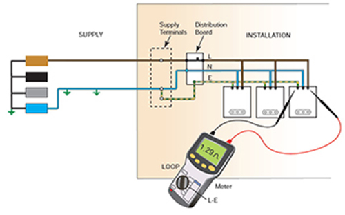
    First, what is the "earth fault loop"?? Have a look at the diagram below and see of you can relate it to what you are testing.

    Next what resistance value do you need to be below to pass?

    Obviously if you reduce the loop the resistance value will reduce as you did by joining the earth and phase together in the board.

    Does this make sense?


    749-2.jpg


  • Registered Users Posts: 2,567 ✭✭✭Risteard81


    It is true that RCDs (including RCCBs and RCBOs) can increase the earth fault loop impedance measured due to the internals - it's not really something to worry too much about. (After all, a 30mA RCD will operate far beyond the impedances of the MCB.) Another problem is test equipment on no trip is notoriously unreliable. Even within the stated accuracy there can be a big difference. If you did a high current loop test with the RCD linked out then simply record that as your value and move on. Don't get hung up on it.


  • Registered Users Posts: 26 BOARDHOG


    What are the limits , is it anything over 1 mega ohm. I work on mostly industrial so it's not easy to switch off a circuit to bypass the rcbo. What answer do you give the client when he questions why there is such a high reading.


  • Moderators, Home & Garden Moderators, Technology & Internet Moderators, Regional East Moderators Posts: 12,595 Mod ✭✭✭✭2011


    You are getting confuse OP:
    Insulation resistance should be high as in mega ohms. Earth fault loop impedance should be low as in a couple of ohms or less.


  • Advertisement
  • Registered Users Posts: 26 BOARDHOG


    Sorry my mistake. What are the acceptable values. Anything under an ohm is great . How far over an ohm can you go.


  • Registered Users Posts: 2,567 ✭✭✭Risteard81


    BOARDHOG wrote: »
    Sorry my mistake. What are the acceptable values. Anything under an ohm is great . How far over an ohm can you go.
    Whilst an RCD will operate with a much greater earth fault loop impedance you would need to be satisfied that the high measured reading was not as a result of loose connections etc. which could cause a fire!

    Realistically, if you are doing this, you should know what the limits are for a device (and really how to work it out even without the tables in front of you). Therefore I am not going to answer that question.


  • Registered Users Posts: 1,051 ✭✭✭Tuco88


    The ETCI have a specific table of values to comply within for each type of protective device.

    The lower the better, less resistance better fault current operating times.

    Sometimes you might be able to meet the requirements by downsizing the protective device.

    Or improve cpc size.


  • Moderators, Home & Garden Moderators, Technology & Internet Moderators, Regional East Moderators Posts: 12,595 Mod ✭✭✭✭2011


    BOARDHOG wrote: »
    Sorry my mistake. What are the acceptable values. Anything under an ohm is great . How far over an ohm can you go.

    Sorry for the various typos / bad grammar, its hard on an iPhone :)

    Your results are not necessarily a fail. You need to understand what you are testing and why.

    First off, why is a low value desirable?
    Short answer: This means a high fault current.

    Why do you want a high fault current?
    Short answer: To ensure that the protective device (MCB or fuse) operates within the required disconnection time.

    What is the required disconnection time?
    Answer; This is stated in the regulations (ET101:2008), from memory (so open to correction here) 0.4 seconds.

    What earth fault loop impedance value will ensure that this disconnection time is met?
    Short answer: That depends on the rating and type of device. As a rough general rule the lower the rating of the device the higher the acceptable earth fault loop impedance.

    How do I know what value is acceptable for a given device?
    Short answer: Several ways, one way is to look it up in ET101:2008

    Is there such thing as a reading that is too low?
    Short answer: Yes there is. You may exceed the breaking capacity of some devices.

    Does this make sense? This is just to give you a few pointers. Some training would be best before doing this on your own.


  • Registered Users Posts: 26 BOARDHOG


    I have recently completed the training coarse. This was obviously a part of the coarse that didn't quite sink in. I need to study the tables in the regs a bit more. No loose connections and I can work out the fault current. Very helpful tips.


  • Advertisement
  • Posts: 5,238 ✭✭✭ [Deleted User]


Advertisement