Advertisement
If you have a new account but are having problems posting or verifying your account, please email us on hello@boards.ie for help. Thanks :)
Hello all! Please ensure that you are posting a new thread or question in the appropriate forum. The Feedback forum is overwhelmed with questions that are having to be moved elsewhere. If you need help to verify your account contact hello@boards.ie
48v/PTT project
Options
-
14-04-2017 1:35am#1I have an urge to make a push-to-talk foot switch with the main use being for gaming. I have yet to get the project box for it but have all the other parts to make it. I will likely use a behringer c3 condenser mic but want to be able to use a gaming head set too so might add 1/4 inch in/out. I have a tube ultra gain for the condenser which has 48v on it and also have 48v on the soundcard I am unsure of where to to add 48v on the signal chain.
If I use the tube the PTT would have to be after the tube where as if I use the soundcard I'm not too sure if the mic will get the 48v. I am using a lead pedal** as the PTT switch and will wire it up like so.
I am assuming the lead pedal has the same wiring internally as the button wiring in the picture, I opened it up seems to. I have a 4 ply cable and was thinking of adding 2 1/8 ins for easy access to the pedal instead of hard wiring it.
If at all possible I'd rather not use the tube as it is noisy AF. The soundcard has decent enough SS pre amps. It could be possible to add the 48v to the box itself but its too much hassle really.
The question is will the 48v reach the mic through the pedal or does anyone know of a way for it to reach it if not. I have very little experience with electronics and 48v for that matter but in researching this little project I think I recall reading that 48v is on hot/cold on an xlr.
Iv'e a feeling it will only pass through when PTT is on which would be bad.
**really solid pedal would recommend it for its intended use.0
Comments
-
Eventide is your friend
https://www.eventideaudio.com/products/accessory/mic-pre-fx-loop/mixinglink
Another cheaper solution might be to use a cheap behringer mixer and hack the channel mute switch to turn the mic on and off.
Building a passive channel and/or IO box ike this that incorporates a phantom supply and a mute is not straightforward as you have to isolate the the phantom from the switching (otherwise BIG thumps) and you need to debounce the mute switch – it requires knowledge of some electronic theory)
Cheers, TM0 -
Eventide is your friend
https://www.eventideaudio.com/products/accessory/mic-pre-fx-loop/mixinglink
Another cheaper solution might be to use a cheap behringer mixer and hack the channel mute switch to turn the mic on and off.
Building a passive channel and/or IO box ike this that incorporates a phantom supply and a mute is not straightforward as you have to isolate the the phantom from the switching (otherwise BIG thumps) and you need to debounce the mute switch – it requires knowledge of some electronic theory)
Cheers, TM
Thanks for the link but I'm not looking to spend big money on it when one can be made for €15. Also would be staying away from those types of switches they make too much noise when they are engaged plus pressing one in bare feet or stockings would be killer.
I think if it is explained well it would be straight forward enough do you have any experience with theory? I read on gearslutz that if you connect pins 2+3 on an xlr that it mutes the audio but lets 48v pass which is what the button above is doing I believe. I don't have much experience with it but its not rocket science either. Is there another thread or forum this would be better in i.e. electronics?0 -
The Eventide has a very light switch and it is noiseless due to the circuitry in there. That's why I suggested it, it meets your need though i take the point about costiLikeWaffles wrote: »Also would be staying away from those types of switches they make too much noise when they are engaged plus pressing one in bare feet or stockings would be killer.")
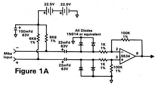
Yes, you need to isolate the mic input from the phantom power so you need two caps in there: one in series with Pin 2 and one in series with Pin 3: signal Hot & Cold respectively. You should also use a pair of 6K8 resistors in series with the phantom supply (prevents 48V supply damage in the event of bad cabling/shorts), and these are connected BEFORE the DC block capacitors referred to above.iLikeWaffles wrote: »I think if it is explained well it would be straight forward enough do you have any experience with theory?
Look at this schematic here, and you can see the topology:
http://ethanwiner.com/spect-1a.jpg
Basically the caps act as a DC block (but let the alternating audio signal through. The phantom is supplied between these caps and the mic connector, i.e., it feeds the mic power but it does not affect the circuit coming after it.iLikeWaffles wrote: »I think if it is explained well it would be straight forward enough do you have any experience with theory? I read on gearslutz that if you connect pins 2+3 on an xlr that it mutes the audio but lets 48v pass which is what the button above is doing I believe. I don't have much experience with it but its not rocket science either. Is there another thread or forum this would be better in i.e. electronics?
Yes, I do and the explanation is above. You don't want to connect pins 2 & 3, I don't think that's an elegant way to mute the mic and I've never seen it done that way on any of the hundreds of consoles I've worked on. Usually the mute button is a DPDT switch: it disconnects the channel from the audio. Sometimes this makes a noise, so that's where buffer amplifiers come in. But then you're into a different level. This is why I suggested hacking your preamp, a much easier and effective solution. As far as online resources, I use Gearslutz and anything I can find online. Most of these make much more sense if you have a working knowledge of basic electronics – there are books and even workshops in Maker labs in Irish cities. You're right that it's not rocket science, but you do need to understand the functions of the devices in the schematics. It's beyond the scope of this forum to provide tutorials, but I'll happily answer specific questions.0 -
The Eventide has a very light switch and it is noiseless due to the circuitry in there. That's why I suggested it, it meets your need though i take the point about cost
Yes, you need to isolate the mic input from the phantom power so you need two caps in there: one in series with Pin 2 and one in series with Pin 3: signal Hot & Cold respectively. You should also use a pair of 6K8 resistors in series with the phantom supply (prevents 48V supply damage in the event of bad cabling/shorts), and these are connected BEFORE the DC block capacitors referred to above.
Look at this schematic here, and you can see the topology:
http://ethanwiner.com/spect-1a.jpg
Basically the caps act as a DC block (but let the alternating audio signal through. The phantom is supplied between these caps and the mic connector, i.e., it feeds the mic power but it does not affect the circuit coming after it.
Yes, I do and the explanation is above. You don't want to connect pins 2 & 3, I don't think that's an elegant way to mute the mic and I've never seen it done that way on any of the hundreds of consoles I've worked on. Usually the mute button is a DPDT switch: it disconnects the channel from the audio. Sometimes this makes a noise, so that's where buffer amplifiers come in. But then you're into a different level. This is why I suggested hacking your preamp, a much easier and effective solution. As far as online resources, I use Gearslutz and anything I can find online. Most of these make much more sense if you have a working knowledge of basic electronics – there are books and even workshops in Maker labs in Irish cities. You're right that it's not rocket science, but you do need to understand the functions of the devices in the schematics. It's beyond the scope of this forum to provide tutorials, but I'll happily answer specific questions.
Thank you for the info. Is that schematic for adding phantom power to a signal that is not supplied? Or is it pulling PP off the chain and routing it to the xlr input so the lead pedal can bypass the audio? I can never understand schematics because of the lack of visuals. This will be my first taste of building something so I want to do it correct.
I don't mind if it is not elegant as long as it functions. Would it work if it was a dynamic mic/had no phantom power. If it's too complicated to use PP I could probably just use a dynamic mic or gaming headset.
There is PTT in most games but I want a foot switch for the extra control and less of the open mic.0 -
iLikeWaffles wrote: »Thank you for the info. Is that schematic for adding phantom power to a signal that is not supplied? Or is it pulling PP off the chain and routing it to the xlr input so the lead pedal can bypass the audio? I can never understand schematics because of the lack of visuals. This will be my first taste of building something so I want to do it correct.
Sure!
Yes, this is a bog standard mic pre w/ phantom schematic from a standard analog console (it's not a pedal). The phantom power supply is not shown. I'm confused by the next sentence – I found this schematic as it shows where the phantom is applied, and where the DC bypass caps sit in relation to the phantom power supply (you need to get this right for your project as you do not want to feed 48V DC into the next stage down the line – at best it will make a lot of noise, more likely it'll burn up the next buffer in the chain. Not a good look :eek:
Familiarity with schematics comes with practice, and they are visual in the sense that they give you a visual of the paths in the circuit. It's not a legend, or a map though. The London Tube Map is a schematic of sorts, it prioritises the functional layout of the tube and the connections. If this is your first project, can I gently suggest that you attempt a simpler project first?iLikeWaffles wrote: »I don't mind if it is not elegant as long as it functions. Would it work if it was a dynamic mic/had no phantom power. If it's too complicated to use PP I could probably just use a dynamic mic or gaming headset. There is PTT in most games but I want a foot switch for the extra control and less of the open mic.
When I said elegant, I was speaking from a functional point of view ( I have some horrible looking builds that sound great ). Your design shorts the input of the next device down the line. It also applies 48 V DC to the inverting and non-inverting inputs of the next stage (unless you take my advice and position the DC bypass caps. At best, you will hear massive thumps every time you hit that switch. You could use a dynamic mic, and try interrupting the hot signal rather than shorting it. Or try hacking the switch on your headset so that you can access it with a footswitch. 0 -
Advertisement
-
Sure!
Yes, this is a bog standard mic pre w/ phantom schematic from a standard analog console (it's not a pedal). The phantom power supply is not shown. I'm confused by the next sentence – I found this schematic as it shows where the phantom is applied, and where the DC bypass caps sit in relation to the phantom power supply (you need to get this right for your project as you do not want to feed 48V DC into the next stage down the line – at best it will make a lot of noise, more likely it'll burn up the next buffer in the chain. Not a good look :eek:
Familiarity with schematics comes with practice, and they are visual in the sense that they give you a visual of the paths in the circuit. It's not a legend, or a map though. The London Tube Map is a schematic of sorts, it prioritises the functional layout of the tube and the connections. If this is your first project, can I gently suggest that you attempt a simpler project first?
When I said elegant, I was speaking from a functional point of view ( I have some horrible looking builds that sound great ). Your design shorts the input of the next device down the line. It also applies 48 V DC to the inverting and non-inverting inputs of the next stage (unless you take my advice and position the DC bypass caps. At best, you will hear massive thumps every time you hit that switch. You could use a dynamic mic, and try interrupting the hot signal rather than shorting it. Or try hacking the switch on your headset so that you can access it with a footswitch.
What about using the switch to bypass the output. So routing it so PP comes in and is split on 2 lines using the second output for the switch to bypass (non existent output/mute) still keeping phantom power going to mic. Phantom output if you will.
Had it worded a little better but asked me if I'm a robot there and lost the wording. I'm not a robot.....0 -
Kinda should work? (disclaimer: I won't be responsible for any injury/damage to your person or your gear)
Hard to tell exactly without seeing a schematic. Technically it's OK to short the 'hot' audio input to the 'cold' audio input at the buffer stage, e.g., some normalised patch bays do this and balanced line inputs on consoles do it too. It's a trick to keep noise down, if the input is tied to ground (or chassis) then it is not free to float round picking up extraneous noise. The switch would need to be placed after the DC blocking caps (you have not mentioned these but you'll need them if you are using phantom!
Or you can use a DPDT switch for a full disconnect. Like here:
https://www.gearslutz.com/board/attachments/geekslutz-forum/464391d1430182622-xlr-jack-bypass-mutebox-schematicback_schem.jpg
You will need to modify this ^ ^ schematic to incorporate the phantom power reqs from the other schematic i gave you.
I still think you'd profit from a visit to Dublin Maker and/or TOG. They have a hackspace and you could hang out there and get advice on your project and on electronics in general
http://www.dublinmaker.ie0


Advertisement