Advertisement
If you have a new account but are having problems posting or verifying your account, please email us on hello@boards.ie for help. Thanks :)
Hello all! Please ensure that you are posting a new thread or question in the appropriate forum. The Feedback forum is overwhelmed with questions that are having to be moved elsewhere. If you need help to verify your account contact hello@boards.ie

Ford Transit conversion to camper MKII

18911131416

Comments

  • Registered Users, Registered Users 2 Posts: 73,477 ✭✭✭✭colm_mcm


    You’ll have great craic cutting out for the smev.

    Be very careful with the wire going to the piezo on the hob. It’s very delicate. I’d unplug it until you’re ready to use it.


  • Registered Users, Registered Users 2 Posts: 6,260 ✭✭✭Buford T Justice


    Oops....the coil control above is for a Delay on relay. Delay On-Off is a little more involved.


    545541.jpg
    Input voltage can be battery.
    The trigger switch would have to be another relay with the coil powered from shore power and the switching dry contacts connected to the "S" on the delay relay.

    Function I on this relay is the same as function H of the GARO. However both need a continuous supply to work for delay on and delay off.
    If input voltage U is the battery and given that the switch S is powered from shore, once the shore energises
    A) Wouldn't that be just bad?
    B) Wouldn't that end up sending 12V to the coil in the contactor rather than 240?


  • Posts: 5,238 ✭✭✭ [Deleted User]


    I started gutting my truck today...I might start a thread.
    I meant to just delete the gas fridge. Then I blazed a trail to almost the back doors.


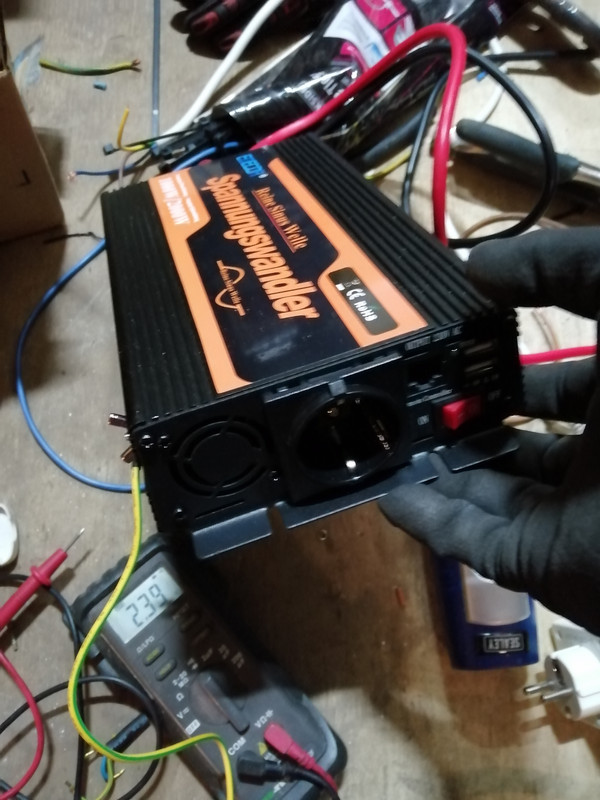
    Oh, and I complained to the supplier about the "faulty" inverter and managed to blag myself a replacement.


    rolleyes.png


    Function I on this relay is the same as function H of the GARO. However both need a continuous supply to work for delay on and delay off.
    If input voltage U is the battery and given that the switch S is powered from shore, once the shore energises
    A) Wouldn't that be just bad?


    S is a dry contact. As in an unpowered switch.
    If you put 230v on it you'll toast it.
    Use another relay that's got a 230v coil and wire S to that other relay's non-energised N.O. terminals.


    B) Wouldn't that end up sending 12V to the coil in the contactor rather than 240?


    Yes, you have a battery charger don't worry about it. If you use 230V the delays can't work unless you keep your inverter running and use that to power it instead which is still battery but waaaay less efficient.


    It's a tiny computer. It runs off 12v, It reads a closing switch as a trigger and then uses the 12v to power the coil.


  • Registered Users, Registered Users 2 Posts: 6,260 ✭✭✭Buford T Justice


    I started gutting my truck today...I might start a thread.
    I meant to just delete the gas fridge. Then I blazed a trail to almost the back doors.

    You should - I'd be interested in seeing it.

    I was feeling a bit under the weather today for self inflicted reasons so I started with some non essential jobs.

    The handbrake lowering kit was top of my list. The last time I was at the batteries I left the clamp out so this had to go back in as well.

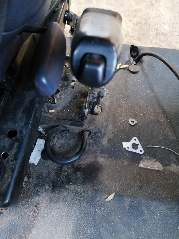
    To start with, the boot around the hanbrake wouldn't sit down right, and it was causing the handbrake light to stay on since it couldn't close the switch properly.
    For some reason the previous owner had pulled out the negative cable into a loop which was causing the problem

    IMG-20210227-172611.jpg

    I pulled the slack back into the battery box to get rid of the loop.

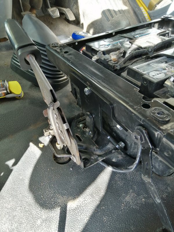
    Aside from that it was really a simple job to do. Three nuts off the side of the battery box, bolt on the bracket to the handbrake and bolt the bracket to the battery box. Job's a good'un

    IMG-20210306-145807.jpg

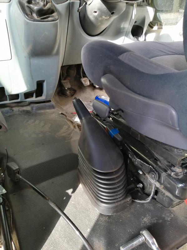
    Cut the excess off the bottom of the boot and put it back on.

    IMG-20210306-150653.jpg

    The seat can now swivel around without having to put the handbrake down, so it was a worthwhile effort.


  • Registered Users, Registered Users 2 Posts: 6,260 ✭✭✭Buford T Justice


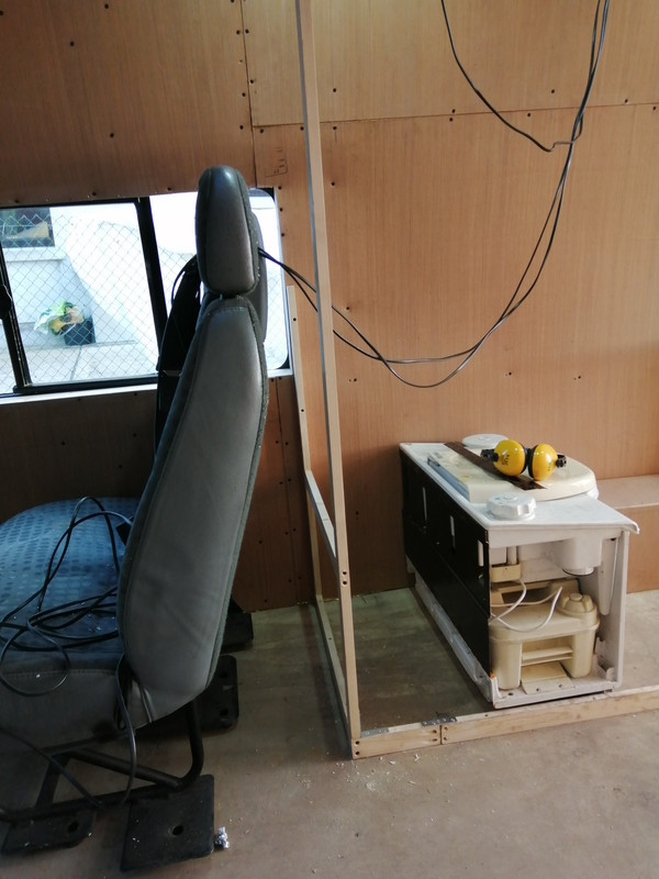
    Added a little to the bathroom wall.

    Having the new sink dimensions makes basic guesswork about sizes easier. I'll have to get some 18mm birch ply to build the cabinets for the kitchen, but the concern around the gap is not an issue now.

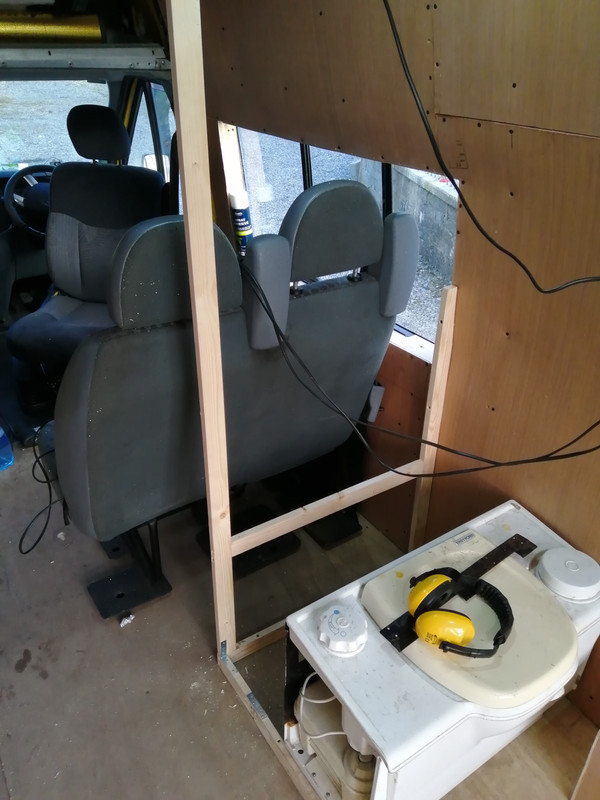
    I've extended the size of the bathroom up to the window. This will bring the seats further forward in the van, which I'm ok with.

    IMG-20210306-172104.jpg

    IMG-20210306-172116.jpg

    The timber is 4mm away from the window opening meaning when the wall panel is added, it'll line up with the window edge. Have added a strut for the toilet bracket too, something I missed in the last van.


  • Advertisement
  • Posts: 5,238 ✭✭✭ [Deleted User]


    You should - I'd be interested in seeing it.


    I knew you'd say that. I think I'll make yee all wait for it a bit longer.:pac:
    I've deleted just about everything between the camper tax disc to the back doors now.


    I'll be putting the thread in the MH forum. :p
    Have a great name for it...


    So far I'm thinking;
    12kVA inverter.
    1/4 ton > 1/2 ton of battery
    1200W > 1500W solar
    16A Inlet (grid-tied, backfeed enabled)
    16A Outlet
    32A Outlet
    16A Three-phase outlet.
    Recirculating solar assisted shower.
    5kW Hydronic Space heating, calorifier with engine coolant feed.
    2kW Diesel Air heater with afterburner.
    Induction hobs.
    Halogen oven.
    Compressor fridge.
    4m Awning.


    No feckin li-ion, apps, clouds or voice activation.
    Aspiring towards no gas.


    And a plethora of mechanical repairs.


    I like the handbrake reduction kit...I need one of those for my air handbrake..


  • Registered Users, Registered Users 2 Posts: 6,260 ✭✭✭Buford T Justice


    I knew you'd say that. I think I'll make yee all wait for it a bit longer.:pac:

    Hey, no fair!
    I've deleted just about everything between the camper tax disc to the back doors now.


    I'll be putting the thread in the MH forum. :p
    That's a dig right there.....:pac::pac::pac:
    Have a great name for it...


    So far I'm thinking;
    12kVA inverter.
    1/4 ton > 1/2 ton of battery
    1200W > 1500W solar
    16A Inlet (grid-tied, backfeed enabled)
    16A Outlet
    32A Outlet
    16A Three-phase outlet.
    Recirculating solar assisted shower.
    5kW Hydronic Space heating, calorifier with engine coolant feed.
    2kW Diesel Air heater with afterburner.
    Induction hobs.
    Halogen oven.
    Compressor fridge.
    4m Awning.


    No feckin li-ion, apps, clouds or voice activation.
    Aspiring towards no gas.


    And a plethora of mechanical repairs.


    I like the handbrake reduction kit...I need one of those for my air handbrake..

    I know I could've done something myself to lower the handbrake, but that plate was only 25 squid and saved so much faffing about it was worth it.

    Ambitious project. What size wagon is it - 7.5T?


  • Posts: 5,238 ✭✭✭ [Deleted User]


    T2 Vario 814. Ex-library.

    It's a clone of my T1 except bigger, better everything...right fancy yolk I've never had a turbo before.

    Ambition tehehe..indeed...€2 sez that'll all actually happen. :D


  • Registered Users, Registered Users 2 Posts: 6,260 ✭✭✭Buford T Justice


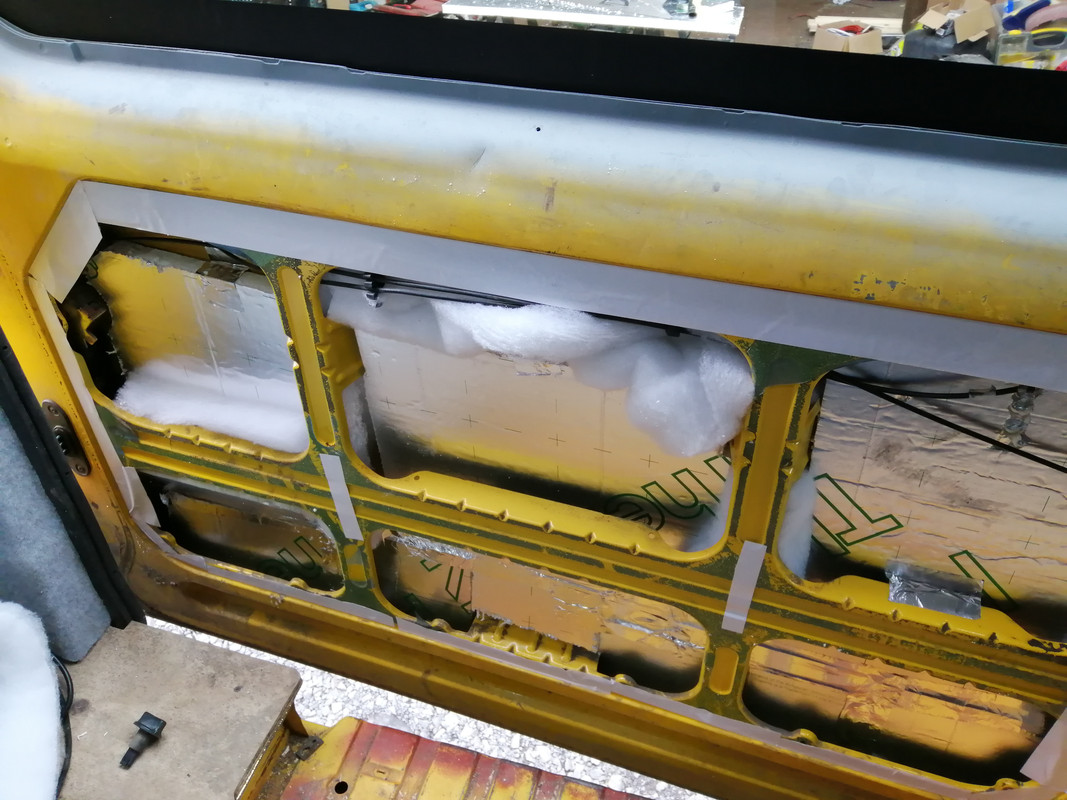
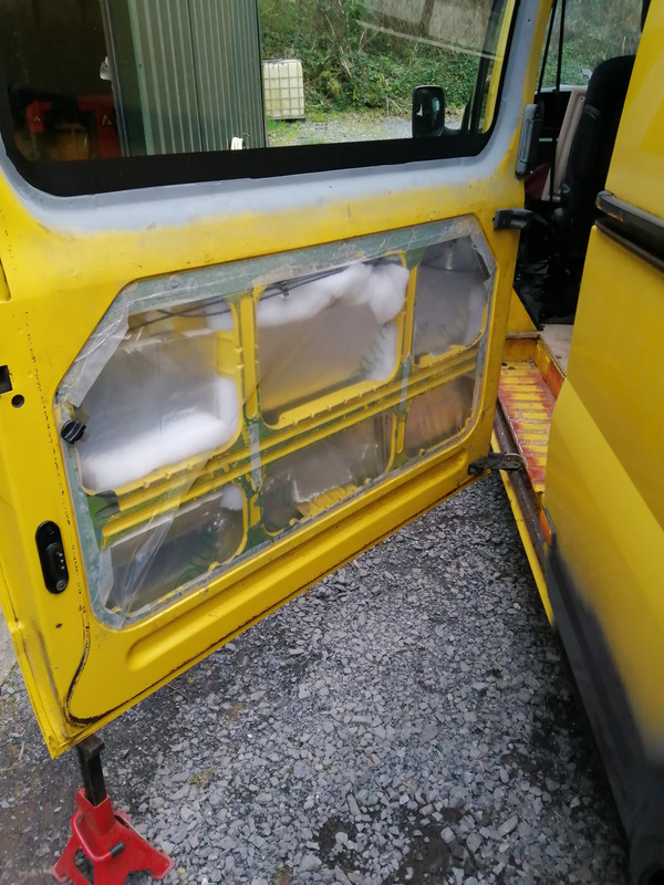
    Insulated the sliding door today. The top of the door has a can of expanding foam inside it too, so hopefully that should make a difference

    IMG-20210307-133247.jpg

    Needed to get the vapour barrier on properly so I took the back hinge off and I was able to get the back of the door out and do it properly,

    I also ran a line of 2mm foam around where the seal goes so when the carpet goes off the edges of the lining of the door inner, there's a thermal break on it.

    IMG-20210307-135533.jpg

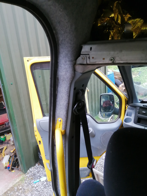
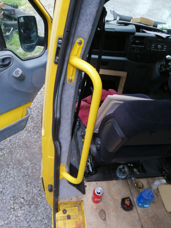
    While I as at it, I finished off around the sliding door all the way down the B pillar. Again, with 2mm closed cell foam and lining carpet over it.
    I had a handle for the pillar so I added that too.

    IMG-20210307-152241.jpg

    IMG-20210307-152235.jpg


  • Posts: 5,238 ✭✭✭ [Deleted User]


    I'm of two minds about vapor barriers. I'm inclined to side on the mitigate condensation route rather than coral it.

    Have you a cheap source for those insulating boards?

    I found the former owner of my yolk is after sawing off 1m of C-pillar to install a window....sigh...Stick welders' a great yolk...I've 4 hours on it...now I need a TIG kit for it..anna bottle of aargon....this campervan thing...expensive habit...


  • Advertisement
  • Registered Users, Registered Users 2 Posts: 6,260 ✭✭✭Buford T Justice


    Other bits and pieces that I got dome today.

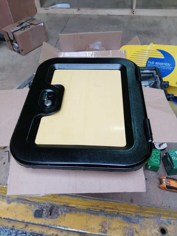
    Primed with plastic primer and I painted the access door for the toilet black. I've no idea if this'll stick to it or not, but it's better than it was. I can always get it powercoated if this fails. Added some body paneling from the window cutouts and it looks the job.

    IMG-20210307-161444.jpg

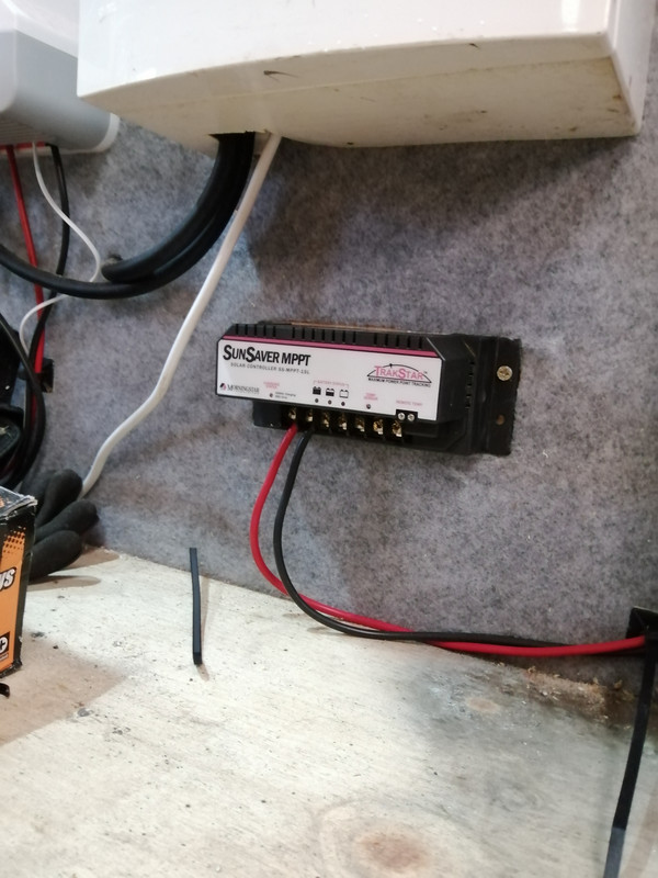
    Fitted the MPPT to my non existent solar panels

    IMG-20210307-165020.jpg


    Finished the insulation all the way to the front of the van. I still don't know how I'll finish that part as of yet, but we'll see what happens closer to the time

    IMG-20210307-165031.jpg

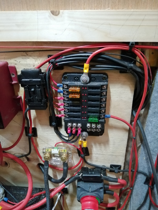
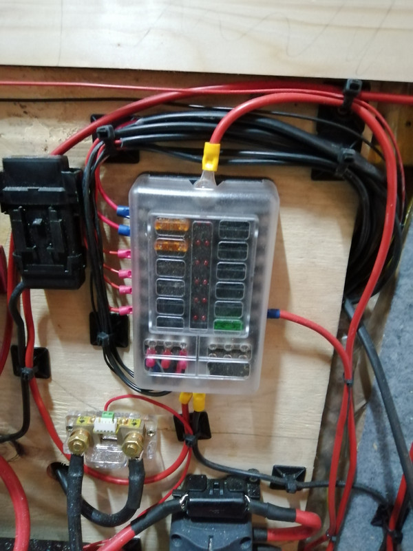
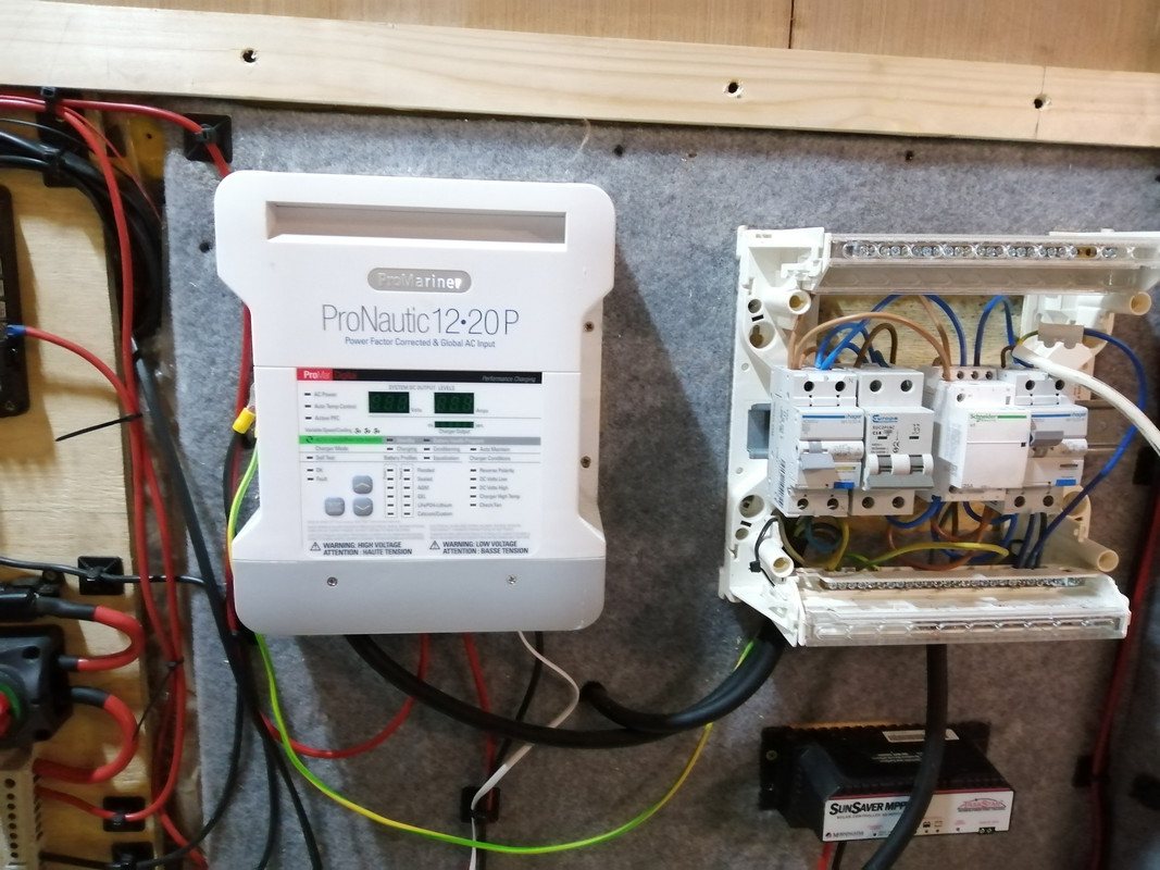
    Tidied up the wiring around the fuse box. Most of these wires aren't terminated to anything as of yet.

    IMG-20210307-175353.jpg

    IMG-20210307-175403.jpg


  • Registered Users, Registered Users 2 Posts: 6,260 ✭✭✭Buford T Justice


    Have you a cheap source for those insulating boards?

    Nope. 28 squid a sheet in my local builders providers.


  • Posts: 5,238 ✭✭✭ [Deleted User]


    PS if ya put some heavy cardboard on the top of yer jack stand and wrap it in automotive loom tape (great stuff) or PVC or whatever it'll save ya allotov paint.


  • Posts: 5,238 ✭✭✭ [Deleted User]


    I've no idea if this'll stick to it or not, but it's better than it was. I can always get it powercoated if this fails.


    I just stone chip all that stuff. I buy 3 gallons at a time.

    Fitted the MPPT to my non existent solar panels


    Didja RTFM yet?
    B+ oughta bypass yer isolator with it's own fuse and isolator (or pull the fuse to isolate if ya wanna cheap out)


    The LVD on that is pretty neat. I use it for all sorts you can also drive relays to control inverters and fridges because it's programmable.


    I often drop a 6-way fuseblock on that output for 15A of non-essential low voltage disconnectable loads.


    I'm trying not to mention all the switchgear you ought to have on the inputs and outputs what'll cost more than you paid for the controller...I'll see if I have any pics..


    Yoink..


    432798.JPG


    Tidied up the wiring around the fuse box.


    546191.jpg


    The-Horror-Of-Bad-Writing-How-Not-To-Get-Your-Guest-Post-Published.jpg


  • Registered Users, Registered Users 2 Posts: 73,477 ✭✭✭✭colm_mcm


    I wonder if you could restore the toilet seat? We got an old thetford the same as yours a few years ago but ended up giving it away - at the time I saw some retro computer fans on YouTube doing a process they called ‘restobright’ which was basically using peroxide and UV light.
    I was going to give it a go but didn’t bother in the end.

    It’s a pity they stopped doing the toilet roll holder on the newer thetford toilets.


  • Registered Users, Registered Users 2 Posts: 6,260 ✭✭✭Buford T Justice


    I just stone chip all that stuff. I buy 3 gallons at a time.

    Good to know if it needs re-doing
    Didja RTFM yet?
    B+ oughta bypass yer isolator with it's own fuse and isolator (or pull the fuse to isolate if ya wanna cheap out)

    Yes, but something tells me that your digestion of the manual is different to mine.

    Are you talking about wiring the charge into the batteries?

    I was going to fuse it and run it direct to the battery

    The-Horror-Of-Bad-Writing-How-Not-To-Get-Your-Guest-Post-Published.jpg

    It's amazing how something can be staring you in the face for infinity and never see it. I have the cable now, that'll go on my to do list.


  • Registered Users, Registered Users 2 Posts: 6,260 ✭✭✭Buford T Justice


    colm_mcm wrote: »
    I wonder if you could restore the toilet seat? We got an old thetford the same as yours a few years ago but ended up giving it away - at the time I saw some retro computer fans on YouTube doing a process they called ‘restobright’ which was basically using peroxide and UV light.
    I was going to give it a go but didn’t bother in the end.

    It’s a pity they stopped doing the toilet roll holder on the newer thetford toilets.

    Funny you should mention that but i've seen the same videos as I was looking to do it with an under counter fridge I acquired before I realised that it'd be too big for the van.

    Toilet roll holder doesn't come out fully. I've a roll of paper stuck in it at the minute. It's handy though - you can pull the whole thing out to see the water level inside the tank :D:D


  • Registered Users, Registered Users 2 Posts: 6,260 ✭✭✭Buford T Justice


    I took a stab at wiring the fuseboard this evening with limited success.

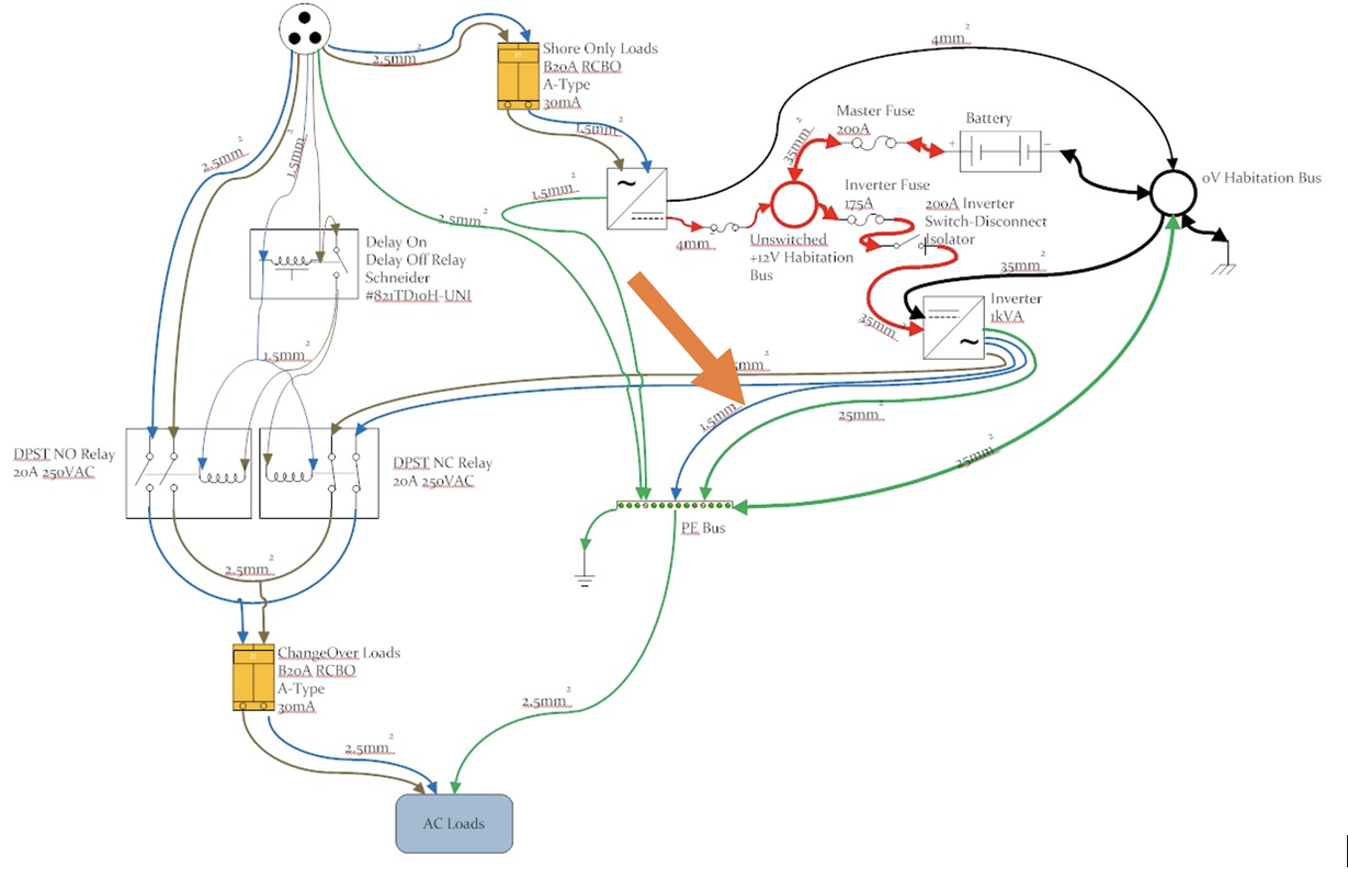
    Following the diagram, I wired the power from shore via the contactor with the exception that it's fed from the output of the MCB for the charger rather than the input so it can be isolated in the van

    For the purposes of this I've left out the time delay

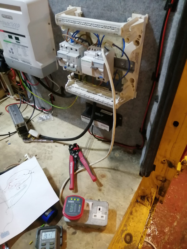
    When the power is applied, the coil is energised, the contacts change and there is 240 at the sockets. No continuity between live & chassis or neutral and chassis from the socket supply.

    No power to the pins on the inverter plug

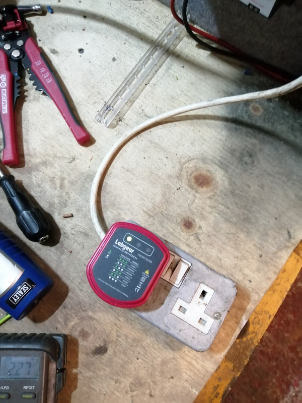
    Tests are good - 3 lights

    IMG-20210309-205336.jpg

    I installed the inverter connection as per, but this is where things went awry.
    Neutral from the inverter supply and earth are both earthed as per the diagram.

    This is the inverter test directly, as expected since there's no earth (no earth spud on the body either), and this wee yoke is only for testing

    IMG-20210309-211746.jpg

    I disconnect the shore power to test the other side and power on the inverter, it immediately sounds an over draw alarm, with no power to the socket tester. There is now continuity between the neutral to the sockets and the chassis.

    If I remove the neutral to earth as indicated below, the inverter powers on no problem
    diag.png

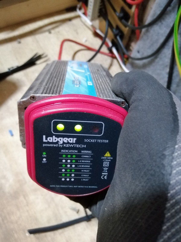
    However, the socket tester is indicating a L -> N reversal.

    IMG-20210309-205942.jpg
    https://i.postimg.cc/dtJg0fVB/IMG-20210309-205942.jpg

    I no longer have the inverter neutral to earth, by why the L -> N reversal?

    I also earthed the Neutral negative from habitation to the earth bus bar

    IMG-20210309-210117.jpg


    I don't get it :confused::confused::confused:


  • Posts: 5,238 ✭✭✭ [Deleted User]


    L + N reversed means nothing if you are floating. You can continuity check instead to verify.

    You might have a L-E L-N fault upstream of the changeover output sending the inverter into overload. You can test that side with shore power and a socket.

    As regards lifting the neutralisation point fault....try again with just a trailing lead and nothing else. Wire the PE to the N of the trailing lead, plug in the tester. Turn on the inverter and see what answer you get.


  • Posts: 5,238 ✭✭✭ [Deleted User]


    I also earthed the Neutral from habitation to the earth bus bar


    Please explain...:confused:


  • Advertisement
  • Registered Users, Registered Users 2 Posts: 6,260 ✭✭✭Buford T Justice


    Please explain...:confused:

    Typeo - I mean to say Negative


  • Registered Users, Registered Users 2 Posts: 6,260 ✭✭✭Buford T Justice


    You might have a L-E L-N fault upstream of the changeover output sending the inverter into overload. You can test that side with shore power and a socket.

    Did this. Power up shore, three lights on the socket tester. Powered off and switched on inverter - inverter overload
    As regards lifting the neutralisation point fault....try again with just a trailing lead and nothing else. Wire the PE to the N of the trailing lead, plug in the tester. Turn on the inverter and see what answer you get.

    Trailing lead out of the RCBO to supply the sockers?


  • Posts: 5,238 ✭✭✭ [Deleted User]


    Did this.


    You unplugged the inverter outlet, and took the plug then in your hand and plugged it into a shore power socket with all other shore power removed from the vessel and the system was ok? {with the neutralization point temporarily lifted}

    Trailing lead out of the RCBO to supply the sockers?


    Get a 13A plugboard. Open the plug. Connect the earth to the neutral. Plug that into your inverter. Have the only thing that is plugged into the plugboard socket end be the socket tester. What answer did you get?


  • Registered Users, Registered Users 2 Posts: 6,260 ✭✭✭Buford T Justice


    You unplugged the inverter outlet, and took the plug then in your hand and plugged it into a shore power socket with all other shore power removed from the vessel and the system was ok? {with the neutralization point temporarily lifted}
    No, I mis-understood what you said


    Get a 13A plugboard. Open the plug. Connect the earth to the neutral. Plug that into your inverter. Have the only thing that is plugged into the plugboard socket end be the socket tester. What answer did you get?

    I'll do both tomorrow evening and report


  • Posts: 5,238 ✭✭✭ [Deleted User]


    You unplugged the inverter outlet, and took the plug then in your hand and plugged it into a shore power socket with all other shore power removed from the vessel and the system was ok? {with the neutralization point temporarily lifted}


    If there is a fault that'll probably trip the supply. Warn the dwellers and bring a torch. There's gentlier ways to test using continuity.

    Get a 13A plugboard. Open the plug. Connect the earth to the neutral. Plug that into your inverter. Have the only thing that is plugged into the plugboard socket end be the socket tester. What answer did you get?

    Actually use a jumper so all three pins are wired. Bridge Earth and neutral.


  • Registered Users, Registered Users 2 Posts: 6,260 ✭✭✭Buford T Justice


    Electric install V2 - Electric boogaloo

    I've been mulling things over the last few days trying to understand what's gone wrong and how this thing works.

    Powered on shore power, and I got 3 lights on the socket tester as I did before.

    I disconnected the wire I was indicating before and and powered on the inverter. Inverter powered up with a L-N reverse fault. I arc'd the earth wire to the neutral as the diagram indicated and there was indeed an arc which shut the inverter down immediately.

    Reverting the install back to the diagram, I re added the wire above

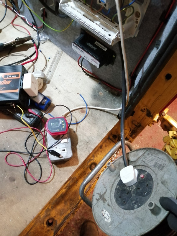
    I plucked up the courage and I plugged shore power in via the inverter plug and got this:

    IMG-20210311-195952.jpg

    3 lights, so I'm confident the install of the inverter is sound.

    The thought occurred to me - maybe my shitty inverter is well... shitty. So I dumped that paperweight and installed my new not as rubbish inverter, grounding the body to the earth of the socket( which is earthed as per diagram).

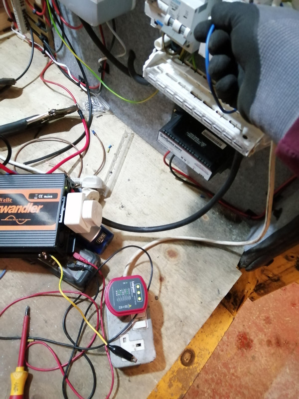
    Powered on the inverter and

    IMG-20210311-200112.jpg

    3 lights again.

    There is no power at the inverter plugs when shore power is energised.
    There is no power at the shore plugs when the inverter is energised.
    There is no continuity between the socket L to the van shell
    There is continuity between the socket N and E to the van shell, but I would expect that they way it's wired.


    So now I'm happy that the install seems to be sound, but I do have a question.

    When shore power is connected, The power detector is flashing and beeping at the RCBO as there is power there. However, there is also a flashing light on the van shell, as per video - although flashing at a lower rate. Clearly I didn't get electrocuted as I'm here to talk about it.


    When the inverter power is connected, there is power detected at the RCBO as expected, but no flashing light at the van shell as per video.


    Why is this, and is it safe?


    Also, the two pin clips on the euro socket in the inverter are earthed to the chassis of the inverter. If the earth of the cable is joined to the bus-bar, is this sufficient earth for the inverter, or should I earth the body directly regardless.

    IMG-20210311-202105.jpg


  • Posts: 5,238 ✭✭✭ [Deleted User]


    I plucked up the courage and I plugged shore power in via the inverter plug and got this:


    If you feed shore into the inverter plug with a N-E bond downstream of your shore outlet then it ought to have tripped the shore RCD.
    That suggests to me there's a defective or no RCD on your shore supply. Or a bad earth.


    3 lights, so I'm confident the install of the inverter is sound.
    The thought occurred to me - maybe my shitty inverter is well... shitty.


    It had occured to me.

    3 lights means the RCD can work...it doesn't mean it does, unlikely it won't but a pro would loop impedance test and check the interrupt times. Expensive test gear for the home gamer. You can get plug in RCD testers...or make one with a shorting resistor.


    There is continuity between the socket N and E to the van shell, but I would expect that they way it's wired.


    That's correct your house is the same albeit with a higher resistance. TN-S ought give you ~ 0v between N - PE and 230V between L and PE. If it doesn't there's an earth loop impedance issue.


    The power detector is flashing and beeping at


    Those things are a liability. Never trust 'em. It might be stray current it might be the moon phase.


    Why is this, and is it safe?


    If you get ~0V between the van chassis and the planet when on shore power then yes. Use a multimeter not a wand.


    Also, the two pin clips on the euro socket in the inverter are earthed to the chassis of the inverter. If the earth of the cable is joined to the bus-bar, is this sufficient earth for the inverter, or should I earth the body directly regardless.


    The earth has to be one gauge smaller than the DC feeder in case It sustains a DC fault across it. Usually that's not practical to do on a 13A socket so I bond the inverter chassis to the DC bus or to the inverter negative battery terminal if you wanna be super lazy.


  • Registered Users, Registered Users 2 Posts: 6,260 ✭✭✭Buford T Justice


    If you feed shore into the inverter plug with a N-E bond downstream of your shore outlet then it ought to have tripped the shore RCD.
    That suggests to me there's a defective or no RCD on your shore supply. Or a bad earth.

    I tried a lot of combinations, so I'm not convinced I had the N-E bonded when I did this

    If you get ~0V between the van chassis and the planet when on shore power then yes. Use a multimeter not a wand.

    Obvious question is obvious, but stick a probe into the floor and t'other on the chassis?


    The earth has to be one gauge smaller than the DC feeder in case It sustains a DC fault across it. Usually that's not practical to do on a 13A socket so I bond the inverter chassis to the DC bus or to the inverter negative battery terminal if you wanna be super lazy.

    I've wired it as per the gauges in the diagram so I'll add an earth bond as per the diagram.


  • Posts: 5,238 ✭✭✭ [Deleted User]


    Obvious question is obvious, but stick a probe into the floor and t'other on the chassis?


    Nope one probe on the van metal and thuther in the mud of planet earth or to an electrode/pole. Volts AC < 10V is good


  • Advertisement
  • Registered Users, Registered Users 2 Posts: 6,260 ✭✭✭Buford T Justice


    Nope one probe on the van metal and thuther in the mud of planet earth or to an electrode/pole. Volts AC < 10V is good

    Measured this today with the earth spike on the shed. Fluctuating between 10 and 12 volts.


Advertisement