Advertisement
If you have a new account but are having problems posting or verifying your account, please email us on hello@boards.ie for help. Thanks :)
Hello all! Please ensure that you are posting a new thread or question in the appropriate forum. The Feedback forum is overwhelmed with questions that are having to be moved elsewhere. If you need help to verify your account contact hello@boards.ie
Hi there,
There is an issue with role permissions that is being worked on at the moment.
If you are having trouble with access or permissions on regional forums please post here to get access: https://www.boards.ie/discussion/2058365403/you-do-not-have-permission-for-that#latest

Solar Panel Project For School

  • 01-04-2022 10:21pm
    #1
    Registered Users, Registered Users 2 Posts: 1,213 ✭✭✭


    Hi

    I am after getting a few solar panel kits (https://irishelectronics.ie/epages/950018241.sf/en_IE/?ObjectPath=/Shops/950018241/Products/EDU02) to teach the basics of circuits and renewable energy with my 5th class students. We also usually do a robotics competition every year and we use a 7.2v battery (https://www.sgeducation.ie/product/vex-iq-robot-battery) in this and I'm thinking about linking the two by setting up a solar panel to charge it. I thought getting a cheap wind turbine might be an option but after reading a few threads on here have put me off. I'm going to try and get some sponsorship locally and get set up using a basic solar panel system.

    So, I need to go from the solar panels to something I can plug the battery charger (https://www.vexrobotics.com/chargers.html) into to power the robot. I've read a lot of the threads on here and I'm hoping that this might be a bit simpler than what you'd need in a house so if anyone can advise me on what I'd need to get or any place to get these basics it would be much appreciated.


«1

Comments

  • Registered Users, Registered Users 2 Posts: 12,131 ✭✭✭✭the_amazing_raisin


    First thing, I love this idea, you could have the solar panels recharging the batteries when the robots aren't being used


    A little solar robot carport would be awesome 😁

    This interesting thing is that the battery charger you showed is that it takes an AC input from the looks of it. There's no spec sheet on the site so it's hard to tell, but looking at the power cords they're including I would expect a brick to convert the AC from the socket to DC if the charger accepted a DC input

    This is the root of the issue, to use that charger you'll need to convert the DC from the solar panel to 230V AC and then the charger will convert this back to DC to charge the battery

    As you can imagine, this is a bit overly complex, and also dangerous as you don't want to be messing around with 230V AC

    Ideally, you could find a small solar panel outputting a bit over 7.2V and connect this to a charge controller for your 7.2V battery. It would be a much simpler setup overall

    "The internet never fails to misremember" - Sebastian Ruiz, aka Frost


  • Registered Users, Registered Users 2 Posts: 1,213 ✭✭✭bungaro79


    Great stuff, thanks for that reply! I just googled "charge controller" there. So am I right in thinking the wire from the solar panel goes into that and then its a case of finding one with the output port I'd need to connect it to my battery?


  • Registered Users, Registered Users 2 Posts: 7,784 ✭✭✭10-10-20


    I like the idea of a solar car-port idea... but keeping away from AC voltages... What about a solar car-port with "power-wall" concept where the solar charges a static battery pack ("power-wall") in the car-port and the vex robot has to detect when it's battery is low and return to the car-port to take a charge?

    So you would effectively go:

    Solar panel (~18v) -> solar charge-controller -> 11.1v (3x 3.7v Li-ion battery-pack).

    The reason I selected 3x 3.7v is that it will give you a working voltage of around 12v which is much easier to obtain charging parts for - such as 12v USB adaptors. Between 6v to 7v v tends to be around the cut-off voltage for many 12v adaptors giving you very little working range.

    Then the charger for the robot (also located in the car-port) could use a buck-converter (DC to DC converter) to step the ~12v down to a level appropriate for the robot's battery (that is assuming that the robot has a charge-controller onboard). I've used this adjustable buck converter from a guy in Ennis as it's got great efficiency: MP1584EN

    Otherwise if you need a charge-controller you can go from 12v (power-wall) to a 5v USB connector and into a charge-controller such as this: https://makershop.ie/Electronics/Power/TP4056-type-C

    Anyway this all depends on the charging methods and voltages available. Don't forget that Li-ion isn't your common-or-garden AA or eve C or D cell, the battery resistance of a Li-ion is much smaller and they don't appreciate being shorted!


  • Registered Users, Registered Users 2 Posts: 12,131 ✭✭✭✭the_amazing_raisin


    Well you could have 2 batteries for each robot and the solar panel charges one while the other is in use. Might be the simplest solution

    "The internet never fails to misremember" - Sebastian Ruiz, aka Frost


  • Registered Users, Registered Users 2 Posts: 12,131 ✭✭✭✭the_amazing_raisin


    Yeah the charge controller converts whatever voltage and current from the panel to the required voltage for the battery. Ideally you'd have something you can just connect directly to the battery cradle to charge the battery. Not sure how easy that will be to find, that Vex battery looks kinda specialised, like a digital camera battery

    "The internet never fails to misremember" - Sebastian Ruiz, aka Frost


  • Advertisement
  • Registered Users, Registered Users 2 Posts: 6,276 ✭✭✭Ubbquittious


    you could 3d print a holder for that battery & charge using programmable charge controller. would save a lot of messing with ac/dc converters.


  • Registered Users, Registered Users 2 Posts: 7,784 ✭✭✭10-10-20


    I'll also add that this site is a fantastic resource and you (as a teacher) can use it as a source for lots of the learning. Even just graphing how batteries discharge along a curve makes understanding easier.


  • Registered Users, Registered Users 2 Posts: 1,213 ✭✭✭bungaro79


    Really appreciate the comments on here. 10-10-20, I think that what you mentioned above regarding the power wall is a great idea. The plan is to look at all the suggestions above and try and teach myself (with a bit of help from another teacher who used to be an electrician!) how to best set this up. We have a 3d printer in the class too so I can use that to make whatever casing is needed.

    Its good to learn about the batteries from the above link too as I'd love to get the lads to make something like a phone charger that they could use in class but I'll start with the robot battery first!


  • Registered Users, Registered Users 2 Posts: 7,784 ✭✭✭10-10-20


    I can't take the credit - lots of good ideas and people with input on here.


  • Registered Users, Registered Users 2 Posts: 1,213 ✭✭✭bungaro79


    So, I'm after buying a few solar panels and plan to experiment around with them over the Easter break. I saw this inverter (https://www.amazon.co.uk/KRI%C3%8BGER-Inverter-Refrigerators-Microwaves-Chainsaws/dp/B07S37S1ZM/ref=sr_1_32?keywords=solar%2Binverter&qid=1649359429&sprefix=solar%2Bin%2Caps%2C136&sr=8-32&th=1) on Amazon. I still plan to try and play around with above suggestions but for now could I do something as basic as hook up the solar panels to this to charge it up and then plug in my battery charger to it?


    Update:

    I'm after watching a few videos on Youtube there (namely this one https://www.youtube.com/watch?v=HOka91PxFlA) and its saying I need a solar charge controller so I can't just hook the inverter up to the panel, right? Can someone explain why the charge controller charges the battery but then it loops back and goes to the inverter?? You can't just hook the inverter to the battery?

    Post edited by bungaro79 on


  • Advertisement
  • Registered Users, Registered Users 2 Posts: 1,213 ✭✭✭bungaro79


    So, I've been doing a lot of research and am slightly more clued in to what I'm hoping to do! I found a really good book on Amazon (https://www.amazon.co.uk/gp/product/1546567119/ref=ppx_yo_dt_b_asin_title_o05_s00?ie=UTF8&psc=1) by a guy who has loads of videos online.

    The set up I hope to use is a 100W solar panel which will be fed into a solar charge controller (an MPPT 75/10, very kindly donated by an Irish company offgridkit.ie) and this will charge a deep cycle battery I bought locally (12V 34 Ah). I have a 500W inverter (and I'm hoping to get a 1000W pure sine one) which I will use to charge my robot battery.

    There's one bit though that I'm still unsure of after reading the book. It seems to be pretty straight forward with most of the connections but he does mention that the wire between the battery and the inverter will take the most amps and therefore needs to be really big. For a 500W inverter he said to use a 10 gauge wire and if you're using a 1000W one then you'd need a 4 gauge wire. A neighbour, who is an electrician, came over to look at my plans but when we converted the wire sizes (https://www.lapptannehill.com/resources/technical-information/metric-to-awg-conversion-chart) he couldn't believe the size that would be needed! He did say that he doesn't really deal in DC connections so I'm hoping someone on here might point out if something above is wrong!

    Post edited by bungaro79 on


  • Registered Users, Registered Users 2 Posts: 7,784 ✭✭✭10-10-20


    Not being negative and not wanting to pull you up on this as I'm sure you have the safety of the students in mind, but is mixing mains voltage and secondary level student projects safe? I'm in two minds about whether it is or not, but you're the best judge. Bear in mind that these inverters have poor or no safety devices and aren't inherently safe just by virtue of their dual 110v sources. They don't have RCD's and absolutely cannot be earthed (unless specifically designed to be).

    4-gauge is 5.2mm diameter or 21.1mm^2 and 1000W at 12v DC = 83A. That's hefty stuff alright, but if you're really aiming to pull anything near the rated power of the inverter, then you need to go for it to reduce the losses in the wire alone. You should be able to source that spec of wire in a motor-factors, or else they'll tell you where to get it. Don't buy it off ebay or other similar vendors, it tends to be sold as copper but can be aluminium instead (AL burns over a lighter flame, CU doesn't).

    Anyway, back to basics: why do you want an inverter? Bear in mind that if you're charging a battery off a battery, the worst plan is to convert that lovely stable 12v DC into 220v AC mains through an inverter just to convert it back into DC at some other low voltage. The efficiency losses for each step are approx 20% and all of the lost power just goes off as heat. Maybe that's actually a good equation for the students to measure and calculate and understand, but otherwise it can be avoided by just converting the 12v into the required battery voltage by using a DC-DC charger. Can you source a suitable 12v or 24v charger instead?

    Come back with questions and ideas, happy to help.

    Post edited by 10-10-20 on


  • Registered Users, Registered Users 2 Posts: 1,213 ✭✭✭bungaro79


    Thanks 10-10-20. Really great advice on there. You're absolutely right about the safety issue. This will be worked on at home and I've 3 electricans who I'll be showing the finished system before it comes into school. If there's any issue from any of them then I won't be risking it. The inverter won't be pulling any hectic amp numbers but I'll look into this more but good tip about the motor factors for these.

    Your last point is what I was hoping to work on after this. I am pretty much going off the book I bought and it is more about running off an inverter but I had seen the DC-DC charger and had planned to work on this after. The only issue with the robot battery I'm planning to charge is that it isn't a standard size and it has to be slid into a charger to work. If there are any DC-DC chargers or places with info on them I'd love to hear it!


  • Registered Users, Registered Users 2 Posts: 7,784 ✭✭✭10-10-20


    So what type is the robot battery? Do you have a part-number and link? Maybe they have their own DC-input charger.


  • Registered Users, Registered Users 2 Posts: 1,213 ✭✭✭bungaro79


    Not sure to be honest. You'll see yourself from the links below that its a connection point rather than a port. It would be great if there was something there I could use directly!


    Battery

    https://www.vexrobotics.com/228-2604.html

    Charger

    https://www.vexrobotics.com/chargers.html


  • Registered Users, Registered Users 2 Posts: 7,784 ✭✭✭10-10-20


    Ah VEX. You linked to that above, but I didn't realise that you were using it.

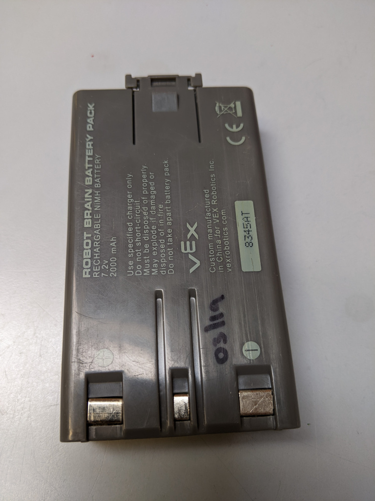
    So that's a 7.2v 2AH battery made up of 6x 1.2v (NiMH - link to battery university) cells in series, with a positive and negative pads and what is probably a charge status (??) connection in the middle. Can you put a multimeter across the terminals and measure the voltage from (-) to the middle connector of the battery? I'm guessing that the battery might have a charge controller within it and potentially that middle pad is the status output for the LED on the charger and there may be no voltage present on it when you read it.

    Li-ION batteries often have a middle pin/connector, but that's used for balancing individual or pairs of cells during charge - but with 6 cells in series in an NiMH pack like that - maybe I'm wrong but I'd hardly think that there would be much point in using balancing at the middle point.

    If you have a dead pack, open the casing slightly and see whether there is a small circuit in the battery pack (I'm talking about opening the plastic casing, not touching the battery cells).

    Anyway, please check what voltage is read between (-) and the small middle pad and if it's coming back as 0v then you could try get a NiMH 7.2v portable/vehicle charger and try a test-charge on a empty battery to see if it takes it (come back to us here before you take that step though).


  • Registered Users, Registered Users 2 Posts: 1,213 ✭✭✭bungaro79


    I'll check that tomorrow as all the stuff is in school. Pretty sure there is one battery pack which is totally dead so I could take that apart and post a photo on here. I just had a quick search for the charger you mentioned above (https://www.amazon.co.uk/7-2v-battery-charger/s?k=7.2v+battery+charger). Which type of those chargers were you thinking? And is this so I could possibly use a DC-DC charger to go directly and not have to use the inverter?

    Thanks again for all the replies


  • Registered Users, Registered Users 2 Posts: 1,213 ✭✭✭bungaro79


  • Registered Users, Registered Users 2 Posts: 1,213 ✭✭✭bungaro79


    Just took these, hope it's what you were looking for!


  • Registered Users, Registered Users 2 Posts: 7,784 ✭✭✭10-10-20


    Yeah, so I was doing a bit of digging... ;)

    Turns out that the middle pin is used by the charger to identify the battery, and that's why you see no voltage from it. But - from what I can understand - the battery isn't locked to the charger, and that means that our plan to use a DC charger still holds some water.

    The theory behind it is that a completely flat battery which is too flat for the charger to recognise will just give a red LED on the charger. But these flat batteries can be recovered using a manual process and these IQ brain systems. To recover the flat battery you connect it up to an IQ brain and connect a motor to one of the ports of the brain and use the motor to generate a small amount of power which is fed back into the battery. After about a min of twisting the motor to charge the battery like this on the IQ, if you then move the battery over to the charger, it should hopefully see the battery and start charging it.

    Anyway, the point is that if you can do that with with a simple motor, there should be little stopping you from charging the battery from a standard 7.2v NiMH DC-input charger... that is if you can find one!

    I'll search out a charger over the coming days, but they appeared elusive during my first search.


  • Advertisement
  • Registered Users, Registered Users 2 Posts: 1,985 ✭✭✭randomname2005


    Great idea and super feedback from others. Mostly replying to keep track of this!


  • Registered Users, Registered Users 2 Posts: 1,213 ✭✭✭bungaro79


    I actually found a video on how to jump the battery a few years back! It saved me a lot of cash as I didn't have to replace them when we returned in September to find them all dead!

    Thanks a million for looking out for the charger for me. To be honest I still am kinda wondering what it will actually look like!


  • Registered Users, Registered Users 2 Posts: 7,784 ✭✭✭10-10-20


    This is one type:

    Looking for one which converts from 12v (or 12/24v) to 7.2v...


  • Registered Users, Registered Users 2 Posts: 1,213 ✭✭✭bungaro79


    Just waiting on my 100w solar panel (these ones are only 10w) to get started!


  • Registered Users, Registered Users 2 Posts: 7,261 ✭✭✭The Continental Op


    Why not use some of the power once you have your 100W panel to power a Raspberry Pi web server and host the notes for the solar project?

    Doesn't need to be on the web just a class WiFi access although that might disadvantage any child without a smartphone.

    Wake me up when it's all over.


  • Registered Users, Registered Users 2 Posts: 1,213 ✭✭✭bungaro79


    Still waiting on the 100w solar panels 😬

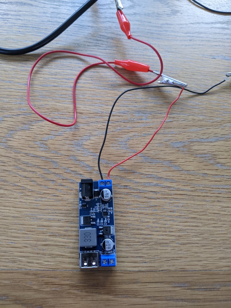
    The direct sun is gone here in Cork but I'm hoping to test this out properly tomorrow. I got a DC-DC converter 12v to 5v today so does this set up look ok? The panel is a 12v 10w. Hoping to try out a phone charger or power bank on it in the sunshine tomorrow 🤞


  • Registered Users, Registered Users 2 Posts: 7,261 ✭✭✭The Continental Op


    That one is on my Amazon wish list https://www.amazon.co.uk/Power-Module-DC-DC-Supply-Converter/dp/B071ZRXKJY/ along with a hundred other bits for ideas for projects.

    I looked up doing something similar on a much larger scale recently and the answer was to use a buck converter so technically that should work. I think it just depends on getting more that 7.8 Volts from the solar panel which is the minimum for that unit to work.

    Wake me up when it's all over.


  • Registered Users, Registered Users 2 Posts: 7,784 ✭✭✭10-10-20


    That 12v to 5v board looks like this one here:

    That's a buck converter alright and it has a pretty good input range of DC 9V--36V. So yeah, ideal for your needs as long as the 100w panel sits around 15v or so.

    Just in terms of wiring - don't skimp on good quality wire when you're working with higher loads later on. Consider using mains cable if you don't have 2.5mm^2 red and black (but label it up very well).

    The other think that you can do is get one of these USB testers - it will allow you to watch the cumulative energy put into a device/battery. Very educational!

    Finally, if you get yourself a variable USB load tester (or just a selection of big resistors), you can test the performance of the power converter.

    Here are some 12v to 5v supplies which I was messing with. The worst obviously was a "Benq" branded board which was so bad that the output voltage dropped to 4.2v at 1A (it was rated for 3.5A, so clearly a failure).

    The Anker PowerDrive was a common USB car-charger, quite impressive.

    Anyhow, all food for thought!


  • Registered Users, Registered Users 2 Posts: 1,213 ✭✭✭bungaro79


    Thanks for the replies. Unfortunately the above set up didn't work today. I had the 1 10W 12V in direct sunshine and then used the same wire set up (crocodile clips onto the wires from the panel and onto small wires which fit into the buck converter). I plugged in my phone and then my power bank but it didn't seem to work for some reason.


    Those links are great. I had actually seen the USB tester on Amazon already and thought it might be useful so I'm glad to see the recommendation!!


  • Advertisement
  • Registered Users, Registered Users 2 Posts: 7,784 ✭✭✭10-10-20


    That might have been the phone if the power quality wasn't good enough. You'll need to measure some of the voltages/currents while it's setup to see if it's working properly.

    • Measure the panel voltage when open-circuit (no devices) and in full sun (preferably not behind glass).
    • Connect up the converter module and re-measure the voltage (should be roughly the same).
    • Put a load on the output of the converter - something between 33 and 80-ohm resistor (for a load of between 63mA and 150mA.
    • Measure the voltage on the panel as well as on the output of the converter module. It should be 5v (+/- 5%) on the converter module and the solar panel should have dropped from the open-circuit voltage too (but still needs to be above 9v).
    • Measure the current on the same ^
    • Then attach a USB device, such as a partially charged portable battery pack, and re-measure all voltages while the pack hopefully pulls up to 500mA.

    We might find the reason for a lack of charge then!


  • Registered Users, Registered Users 2 Posts: 1,213 ✭✭✭bungaro79


    Brilliant. Thanks for that. I'll try that over the next few days when there's hopefully a bit of good sunshine here!


  • Registered Users, Registered Users 2 Posts: 1,213 ✭✭✭bungaro79


    Tried to put a load on the buck convertor (but not sure if I did it right!) and unfortunately I didn't seem to get any reading


  • Registered Users, Registered Users 2 Posts: 7,784 ✭✭✭10-10-20


    Doh! You'll have to test it using a bench power-supply or a 12v supply with a 2.5mm jack.

    Just feed in 12v and connect that resistor (100 ohm) up to the output screw-terminals directly (ditch the wires for the moment). Then with the multi-meter (MM), measure the input voltage off the top of the screw-terminals (just to check that the MM is working) and then test the output the same way too (should see 5v). If you don't see 5v, you may have a dud buck converter.


  • Registered Users, Registered Users 2 Posts: 1,213 ✭✭✭bungaro79


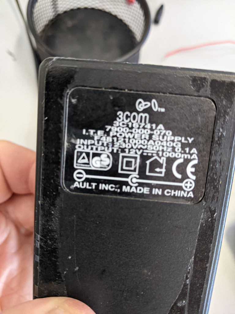
    After googling "bench power supply" (this is the level of novice you're dealing with :D ) and searching around the house for a 12v supply (most of the plugs with the 2.5mm jack seem to be only 6v) I came up with nothing so I'll have to wait till Monday when I can check back in school where I'm pretty sure I have a 12v supply lead.

    Thanks for the basic steps in how to test. Really looking forward to showing the class all about this once I finish testing this. Going to use the lovely sunshine today to link up the two panels I have in series and parallel and see if I get the hang of it!


  • Registered Users, Registered Users 2 Posts: 7,261 ✭✭✭The Continental Op


    House 12V supply - car battery? OK so its going to be a bit over 12 V but I did see one in one of your earlier pictures.

    Wake me up when it's all over.


  • Advertisement
  • Registered Users, Registered Users 2 Posts: 1,213 ✭✭✭bungaro79


    I didn't think of that as a testing source! But I actually left it in school with the inverter and charge controller as I'm still waiting on the solar panels.

    So if I do try and use that 12v battery as my testing current, what kind of connection would I use from the battery? I've been looking online to see something with two wires that comes off the battery and goes into the barrel jack but can't seem to find anything.


  • Registered Users, Registered Users 2 Posts: 7,261 ✭✭✭The Continental Op


    I was only thinking of the 12V battery as a lateral thinking type of source of power.

    I'd use one with big battery type crocadile clips and a circuit with a fuse in it. FUSE is important! You have a store of power that you don't want to dump into a short circuit without some protection.

    You can also use any battery terminals, loads on Amazon but as I said don't forget the fuse, you can't turn a battery off like a power supply plugged into a socket.

    Amazon has loads of cheap bench power supplies for example https://www.amazon.co.uk/Adjustable-Switching-Precision-Charging-Interface/dp/B09C8LWV9W/ handy as they are normally over current protected and you can dial up whatever voltage you require for testing.

    Wake me up when it's all over.


  • Registered Users, Registered Users 2 Posts: 1,213 ✭✭✭bungaro79


    I think getting a 12v plug might be easier so! Thanks for the info though. Great to get all the advice


  • Registered Users, Registered Users 2 Posts: 7,784 ✭✭✭10-10-20


    We'll make an electronic engineer out of you yet.

    Most routers or internet boxes have 12v supplies with 2.5mm plugs. That's if you can live without internet while testing this. ;)


  • Registered Users, Registered Users 2 Posts: 7,261 ✭✭✭The Continental Op


    OP if you are making up "experiments" then these plugs for low voltage stuff might be handy for making up cables https://www.amazon.co.uk/LightingWill-Barrel-Connector-Adapter-Security-10Pair-Female-Male-DC-adaptor/dp/B077YGV3F4/ . That size connector is fairly universal and fits a lot of 12V (and other) wall wart power supplies making the connections available as two screw terminals. You'll note it's also the same size connection on the buck convertor. There are lots of other possible cable plugs you can use but sometimes its easier to get away from crocodile clips particularly if you want the polarities to be right each time.

    Edit> Just a thought you could do a class request for any old unused power supplies might net you a few useful ones?

    Wake me up when it's all over.


  • Advertisement
  • Registered Users, Registered Users 2 Posts: 7,784 ✭✭✭10-10-20


    I'd be wary of "any old power-supplies" these days. BigClive has been an eye-opener in that respect.


  • Registered Users, Registered Users 2 Posts: 1,213 ✭✭✭bungaro79


  • Registered Users, Registered Users 2 Posts: 1,213 ✭✭✭bungaro79


    Great stuff. I'll take any recommendations ye give me!


  • Registered Users, Registered Users 2 Posts: 1,213 ✭✭✭bungaro79


    So, I only got around to testing the buck convertor today as it's been manic with school tours and sports days and all the end of year stuff!

    I found an old 12v charger from our coderdojo router. I put in the 100 ohm resistor and plugged in the charger and then the smoke came 😂

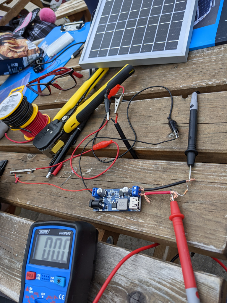
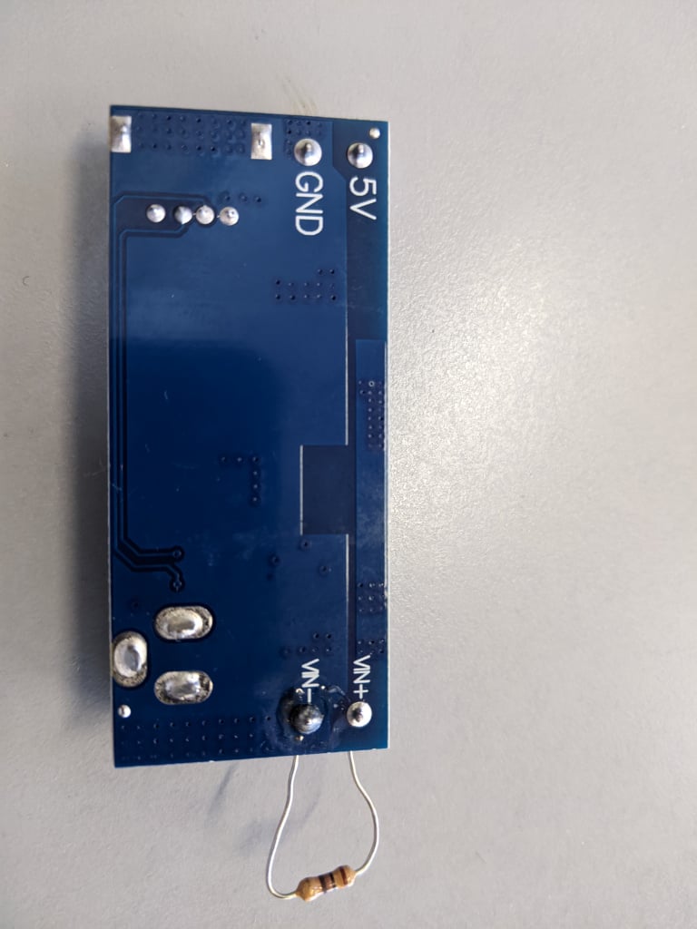
    Does the set up below look ok?!?!


  • Registered Users, Registered Users 2 Posts: 7,784 ✭✭✭10-10-20


    Did you mean to have the resistor on the 12v input of the power-board? That barrel connector and the "VIN-VIN+" are directly connected.

    100 ohm @ 12v = (120mA / 1.44W) = smoke. (a fully balanced equation ;) )

    So yes, that was expected as that resistor is probably rated at 0.25W and you put 1.44W through it. That's fine as a test of 12v.

    Now put a 100ohm resistor on the 5v output of the power-board. It should still heat up, but you'll only be putting in 0.25W (50mA).

    If you can then measure 5v on the output of the board, then it confirms that the board is ok!

    https://ohmslawcalculator.com/ohms-law-calculator


  • Registered Users, Registered Users 2 Posts: 1,213 ✭✭✭bungaro79


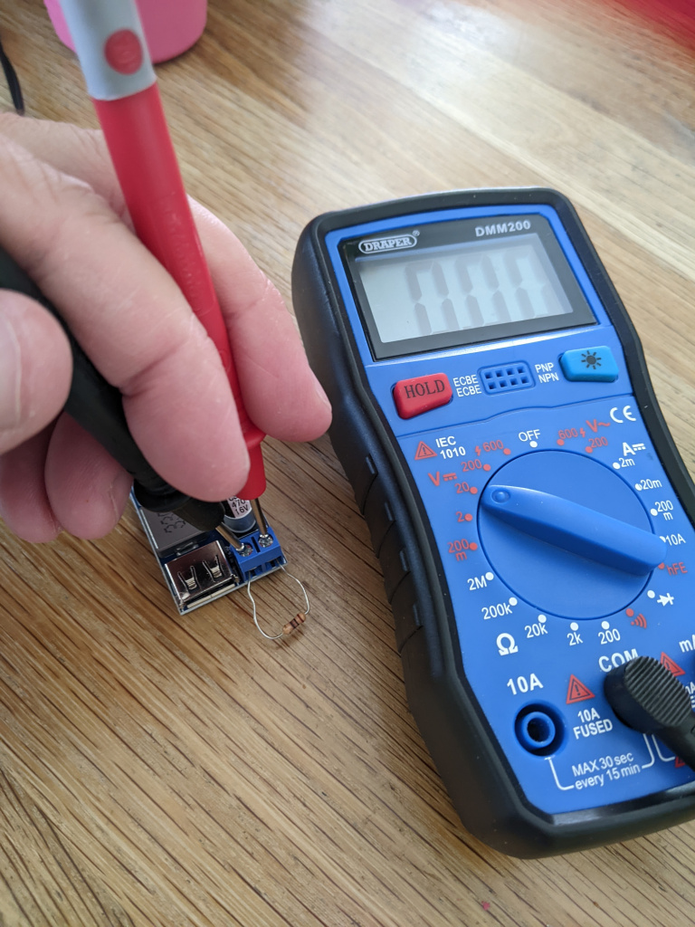
    Ok. Think I did it correctly this time 😅

    It's coming out at 0 reading on the multimeter


  • Registered Users, Registered Users 2 Posts: 7,784 ✭✭✭10-10-20


    If you have 12v on the input and even with a blown resistor there, you should be seeing 5v on the output. I'd suggest that you have a blown DC to DC converter board. 😕

    Maybe no fault of you own. That's why I usually buy two of those at a time.


  • Registered Users, Registered Users 2 Posts: 1,213 ✭✭✭bungaro79


    Cool. Think I'll return it so and order two like you recommended.


  • Registered Users, Registered Users 2 Posts: 1,213 ✭✭✭bungaro79


    Just to keep me tipping away I'm trying one other little project!

    I saw a solar powered clock on instructables.com and it looks really interesting as it uses a super capacitor to power it.

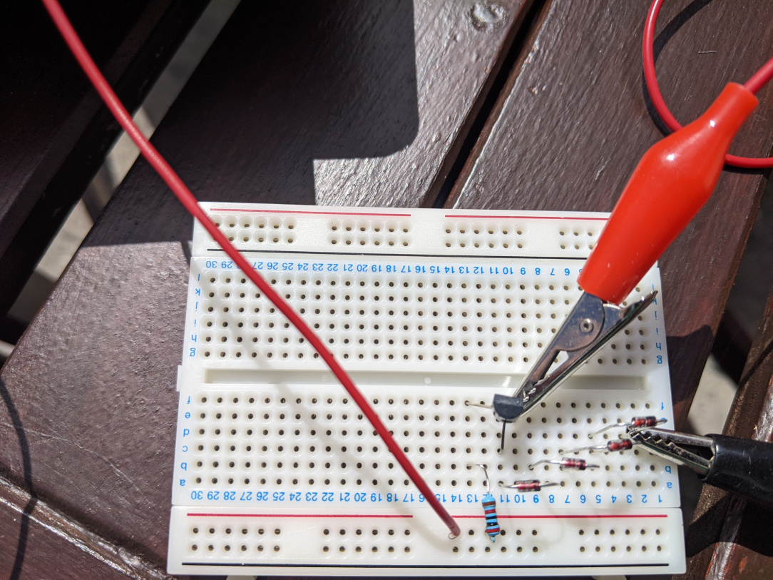
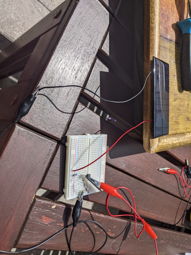
    I think I've the set up correct but can anyone cast their eye over this and see if my set up is right? Hoping to bring it into the class next week while I'm waiting on the new buck convertor and the solar panels


  • Registered Users, Registered Users 2 Posts: 1,213 ✭✭✭bungaro79


    I don't need to hook up the supercapacitor to the clock until its fully charged according to the instructions. I also had to use a 20k resistor as I didn't have any 22k ones.


    https://www.instructables.com/How-to-Run-a-Battery-Clock-on-Solar-Power/


  • Advertisement
Advertisement